Installation: Water Piping
CVHH-SVX001A-EN 25
Evaporator and Condenser Water
Piping
Figure 12 and Figure 13, p. 25 illustrate the recommended
(typical) water piping arrangements for the evaporator
and condenser.
Piping must be arranged and supported to avoid stress on
the equipment. It is strongly recommended that the piping
contractor does not run pipe closer than 0.91 meters
(3 feet) minimum to the equipment. This will allow for
proper fit upon arrival of the unit at the job site. Any
adjustment that is necessary can be made to the piping at
that time. Expenses that result from a failure to follow this
recommendation will not be paid by Trane.
Water piping connection sizes and components are
identified in
Tab le 4, p . 26 and Table 5, p. 27. Remember
that with many waterboxes the entering and leaving
evaporator water can be piped to either waterbox
connection when the tube bundles are split vertically.
However, large evaporator waterboxes, with entering and
leaving connections not at the same level, must be
connected with the entering water at the bottom and the
leaving water at the top.
Waterboxes with multiple pass arrangements utilize a
baffle to separate the passes. These baffles are designed
for a maximum pressure of 137.9 kPad (20 psid). If larger
pressure drops are expected in the application, contact
your local Trane representative to discuss special
waterbox options.
Important: Water flows must be piped in accordance
with nameplate designation.
Field-provided isolation valves for the evaporator and
condenser water lines should be installed upstream and
downstream of the heat exchangers, and be installed far
enough away from the chiller to also provide practical
service isolation for flow sensing devices, field
thermometers, flexible connectors, and any removable
pipe spools.
Ensure that the evaporator water piping is clear, check it
after the chilled water pump is operated but before initial
chiller start-up. If any partial blockages exist, they can be
detected and removed to prevent possible tube damage
resulting from evaporator freeze-up or erosion.
For condenser and large evaporator connections, arrange
the water piping so that the water supply enters the shell
at the lower connection, and exits from the top connection.
Operational problems may result if this piping is not
correct. Some shells may be piped as desired since both
connections are at the same level.
For applications that include an “ infinite source” or
“ multiple-use”, cooling condenser water supply, install a
valved bypass “ leg” (optional) between the supply and
return pipes. This valved bypass allows the operator to
short-circuit water flow through the cooling condenser
when the supply water temperature is too low.
Note: System refrigerant pressure differential must be
maintained above 20.7 kPad (3 psid) at all times.
Failure to do so could result in operating problems.
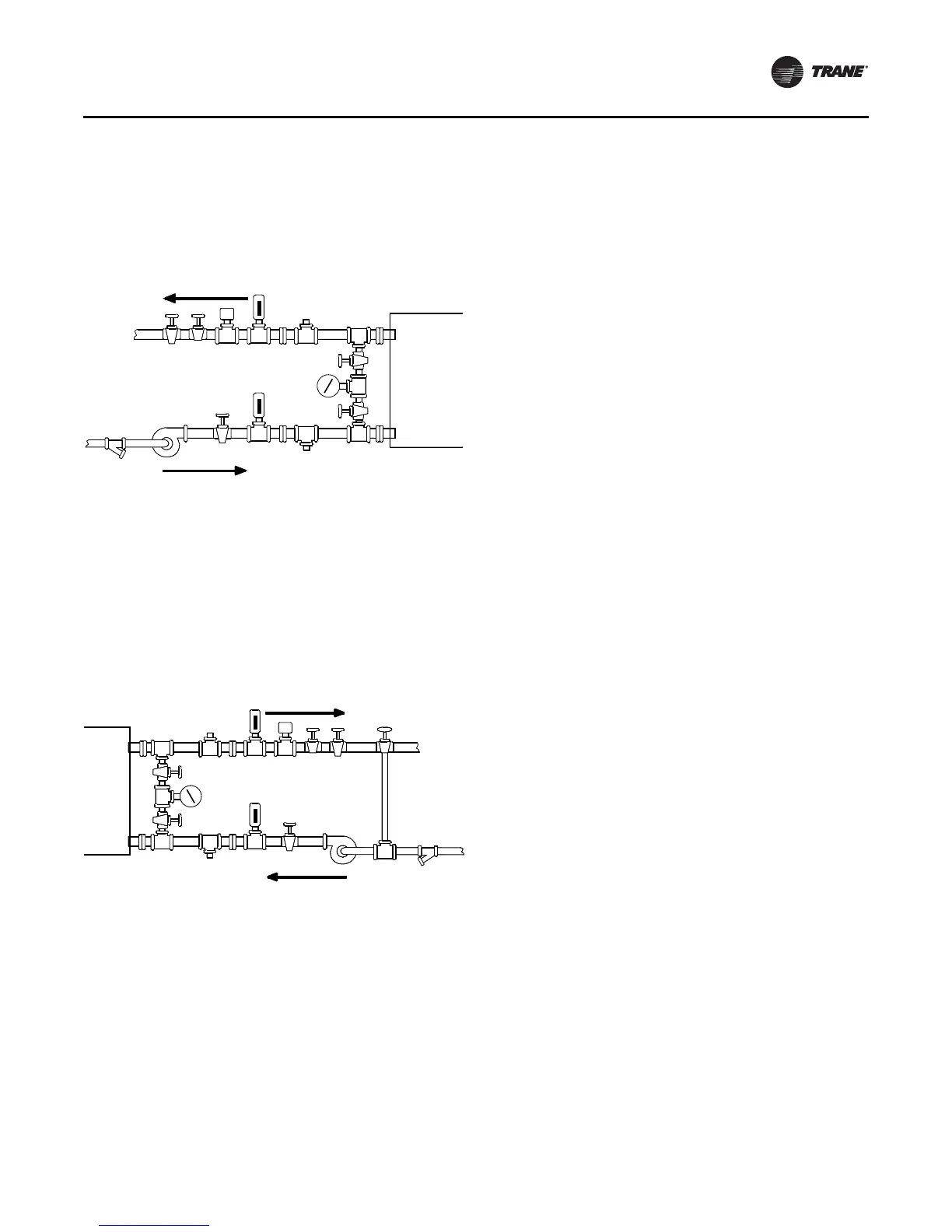
Figure 12. Typical evaporator water piping circuit
1. Balancing Valve
2. Gate (Isolation) Valve or Ball
Valve
3. Thermometer (if field supplied)
4. Waterbox Nozzle Connection
5. Drain, Vent, Anode
6. Strainer
7. Chilled Water Flow Switch
(4B4)
(a)
8. Pump
9. Pressure Gauge
(b)
(a) Flow switch 4B4 may be installed in either the entering or leaving leg
of the chilled water circuit.
(b) I t is recom mended to pipe the gauge between entering and leaving
pipes. A shutoff valve on each side of the gauge allows the operator to
read either entering or leaving water pressure.
Figure 13. Typical condenser water piping circuits
1. Balancing Valve
2. Gate (Isolation) Valve or Ball
Valve
3. Thermometer (if field supplied)
4. Waterbox Nozzle Connection
5. Drain, Vent, Anode
6. Strainer
7. Condenser Water Flow
Switch (4B5)
(a)
8. 3-Way Valve (Optional)
9. Condenser Water Pump
10. Pressure Gauge
(b)
(a) Flow switch 4B5 may be installed in either the entering or leaving leg
of the water circuit.
(b) It is recom m ended t o pipe a single gauge bet ween ent ering and leaving
pipes.
Notes:
1 . Some type of field-supplied temperature control device may be
required to regulate the temperature of the heat-recovery condenser
water circuit. For application recomm endations, refer to Heat
Recovery Seminar (Part 2): "System s/ Equipment (AM-FND-8).
2 . I nstall a bypass valve system to avoid circulating water through the
auxiliary shell when the unit is shut down.
3 . On multiple pass condensers, entering condenser water must enter at
the lowest nozzle.
44
445
5
3
3
7
2
21
9
6
2
2
8
Outlet
Inlet