Installation: Water Piping
24 CVHH-SVX001A-EN
Note: Graphic labels (shown above) are used for CE
application only.
Important:
• Before servicing, disconnect all power sources and
allow at least 30 minutes for capacitors to discharge.
• All electrical enclosures—unit or remote—are IP2X.
5. Apply power to the chiller control panel to verify the
Flow Control Monitor has power and the Low Volt
Broken Wire Relay light is not lit.
6. Remove all air from the piping circuit prior to adjusting
the low water flow setpoint.
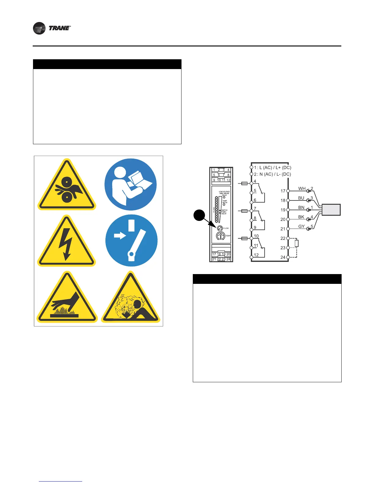
7. Reduce the water flow to the minimum allowable flow
and adjust the Flow setting on the Flow Control
Monitor (see item labeled “ 7” in
Figure 11). Adjusting
the “ Flow” potentiometer clockwise (+) reduces the
flow setting cutout and adjusting counterclockwise (-)
increases the flow setting cutout.
Note: The “ Temp” potentiometer on the ifm efector
control module has no effect in Trane
application. It is not necessary to make
adjustments to the “ Temp” potentiometer.
8. Once the cutout setting is adjusted, the cutout setpoint
will be indicated w ith a yellow light on the Flow Control
Monitor LED bar graph display. When the water flows
are higher than the cutout, a green light will indicate
proper flow status. If the flows fall below the cutout
setpoint, a red light will indicate low/no flow status.
Evaporator and condenser proof of flow switches are
required. These switches are used with control logic to
confirm flow prior to starting a unit and to stop a running
unit if flow is lost. For trouble shooting, a viewable
diagnostic is generated if a proof of flow switch does not
close when flow is required.
NOTICE:
Do Not Apply Electrical Power to a Unit in
a Vacuum!
Failure to disconnect power to units with
inside-the-delta solid state starters during evacuation
or when the unit is in a deep vacuum could cause
compressor motor damage. Applying electrical power
to a motor in a vacuum could cause damage to the
motor. In addition, on units with inside-the-delta solid
state starters, all power to the unit must be
disconnected prior to evacuating the unit as line power
is directly applied to the motor terminals 4, 5, and 6.
Figure 11. ifm efector flow sensing device terminal
connection
NOTICE:
Proof of Flow Switch!
Evaporator and condenser water circuits require proof
of flow switches.
• Failure to include the proof of flow devices and/or
jumping out these devices could cause the unit to
stop on a secondary level of protection.
• Frequent cycling on these higher level diagnostic
devices could cause excessive thermal and pressure
cycling of unit components (O-rings, gaskets,
sensors, motors, controls, etc.) and/ or freeze
damage, resulting in premature failure of the chiller.
Failure to provide flow switches or jumping-out of
switches could result in severe equipment damage.