Installation: Water Piping
CVHH-SVX001A-EN 23
efector,” p. 23) are used to verify evaporator and
condenser water flows.
If a customer-supplied flow sensing device is used to
ensure adequate chiller protection, refer to the wiring
diagrams that shipped with the unit for specific electrical
connections.
Be sure to follow the m anufacturer’s recommendations for
device selection and installation.
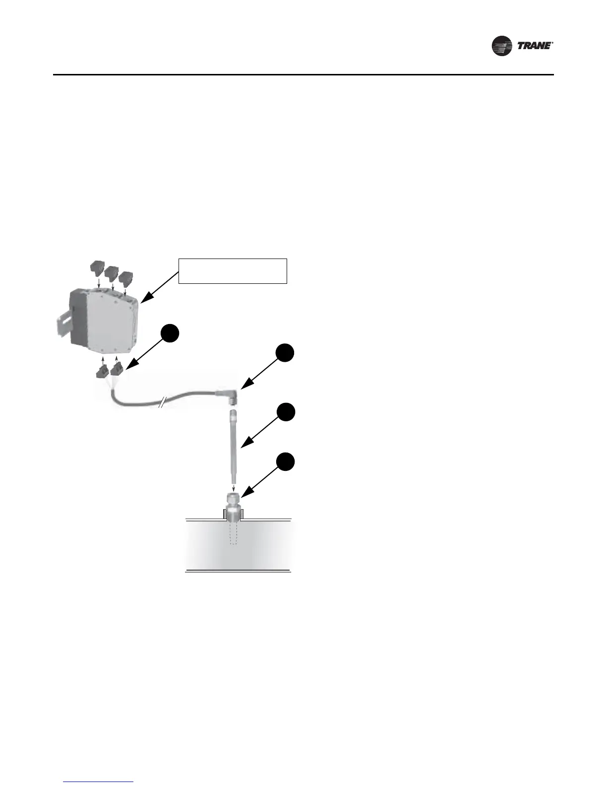
Water Flow Detection Controller and Sensor—ifm
efector
1. Mount the 1/2-in. NPT adapter in a horizontal or
vertical section of pipe. The maximum distance from
the control panel must not exceed 8.99 meters (29.5 ft)
(see item labeled “ 1” in
Figure 10, p. 23). Allow at least
five pipe diam eters straight run of pipe upstream of the
sensor location, and three pipe diameters straight run
of pipe downstream of the sensor location.
Note: In the case of a horizontal pipe, mounting the
sensor in the side of the pipe is preferred. In the
case of a vertical pipe, mounting the sensor in
a place where the water flows upwards is
preferred.
2. Insert the flow probe through the 1/2-in. NPT adapter
as near the center of the pipe as possible (see item
labeled “ 2” in
Figure 10, p. 23). Finger-tighten the
1/2-in. NPT adapter; then, tighten with a wrench an
additional 1-1/4 turns.
Note: When installed, the tip of the ifm efector sensor
probe must be at least 2.54 cm (1 in.) away from
any pipe wall. Placing the tip of the probe at the
center of the pipe is preferred.
3. Install the Micro DC Cable by inserting it through the
wire openings on the back side of the control panel (see
item labeled “ 3” in
Figure 10, p. 23). Install the
supplied Micro DC Cable (9 meters [25 feet] in length)
to the Flow Probe and hand-tighten the connector nut.
4. Plug the other end of the Micro DC Cable into the Flow
Control Monitor with the Combicon connector (see
item labeled “ 4” in
Figure 10, p. 23). Refer to Figure 11
for cable wiring.
Figure 10. Installation of ifm efector flow detection
controller and sensor
Components:
A. E40174 – 1/2" NPT adapter (for ow probe)
B . SF6200 – Flow probe
C . SN0150 – Flow control monitor
D. E70231 – Combicon connectors (quantity 5)
E . E10965 – Micro DC cable, 10m length, PUR jacket
F. F53003 – Din rail, 40mm length
Output to
control cabinet
Jumper
N
L
AC
Jumper
toring
monitoring
re monitoring
delay time
quid / gas
onitoring can
rated using
1, and 12.
w monitoring
monitoring
n series, use
ram at right.
n
pter (A) into pipe.
w probe (B) into adapter (A).
rail (F) into control cabinet.
trol monitor (C) onto DIN rail (F).
able (E) to ow probe (B), (hand tighten only).
in combicon connectors (D) according to
gram.
outputs for ow, wire-break, and/or
ure monitoring, according to wiring diagram.
4
3
2
1
If factory-provided,
located in control panel.