Operating Principles
70 CVHH-SVX001A-EN
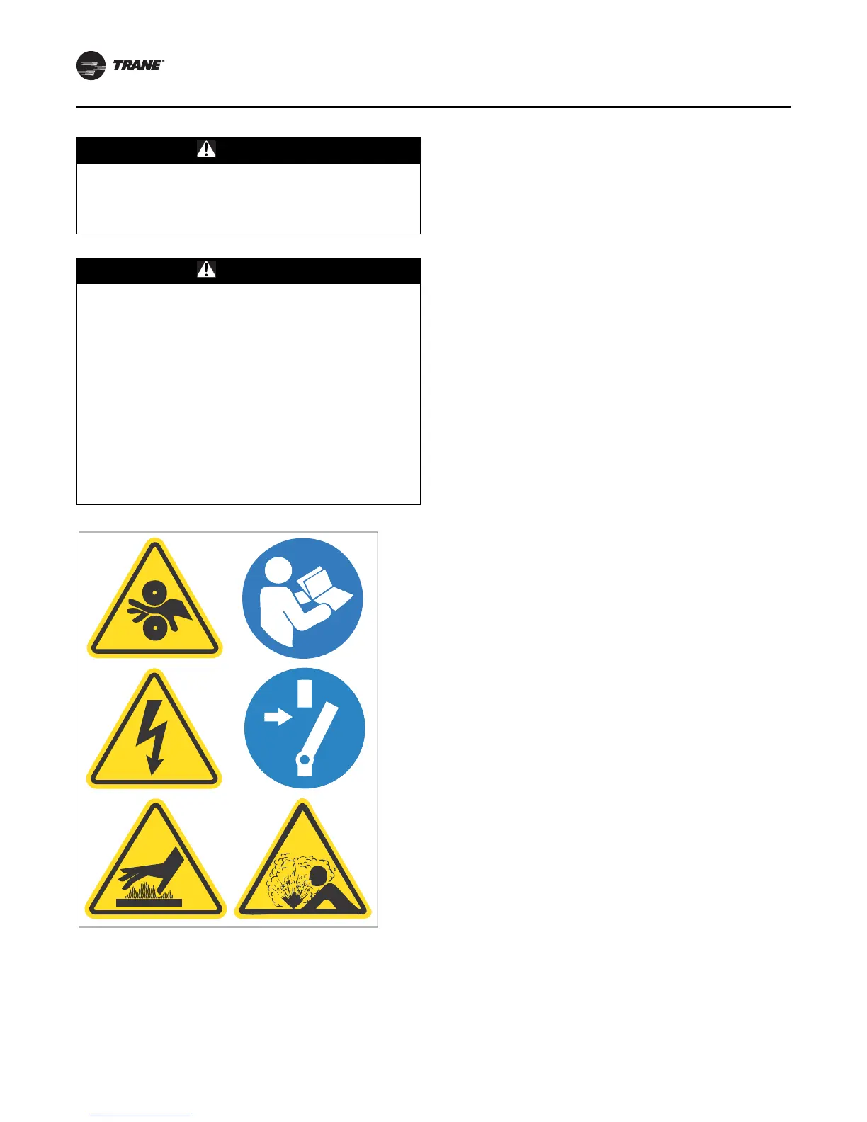
Note: Graphic labels (shown above) are used for CE
application only.
Important:
• Before servicing, disconnect all power sources and
allow at least 30 minutes for capacitors to discharge.
• All electrical enclosures—unit or remote—are IP2X.
To ensure proper lubrication and prevent refrigerant from
condensing in the oil tank, two 750-watt heaters are in
wells in the oil tank and are used to heat the oil while the
unit is off. With the default settings, the oil heaters are de-
energized when the unit starts. The heaters energize as
needed to maintain 53.3°C to 56.1°C (128°F to 133°F) when
the chiller is not running.
When the chiller is operating, the temperature of the oil
tank is typically 37.8°C to 60.0°C (100°F to 140°F). The oil
return lines are routed into a separation chamber in the oil
tank. Gas flow exits out the top of the oil tank and is vented
to the evaporator.
A dual eductor system, using high pressure condenser
gas, reclaims oil from the suction cover and the
evaporator. The suction cover eductor is discharged into
the evaporator, and the evaporator eductor is discharged
into the oil tank. The evaporator eductor line has a shut-off
valve mounted on the evaporator. Normally, the valve
should be 3/4 to one turn open. Open up to two turns if
necessary.
Oil supply to both the thrust bearing and journal bearings
is cooled when the oil tank temperature reaches 60.0°C
(140°F). The supply oil and li quid refrigerant are pumped
to a brazed plate heat exchanger. The unit controller
monitors oil tank temperature and opens a solenoid valve
to allow liquid refrigerant to flow into the heat exchanger.
Motor Cooling System
Compressor motors are cooled with liquid refrigerant (see
Figure 38, p. 69). The refrigerant pump is located on the
front of the oil tank (motor inside the oil tank). The
refrigerant pump inlet is connected to the well at the
bottom of the condenser. The well design ensures
preferential supply of liquid refrigerant to the refrigerant
pump before refrigerant is supplied to the economizer.
Refrigerant is delivered to the motor via the pump. An in-
line filter is installed (replace the in-line filter only with
major service). Motor refrigerant drain lines are routed to
the condenser.
Tracer AdaptiView Display
Information is tailored to operators, service technicians,
and owners.
When operating a chiller, there is specific information you
need on a day-to-day basis—setpoints, limits, diagnostic
information, and reports.
Day-to-day operational information is presented at the
display. Logically organized groups of information—
chiller modes of operation, active diagnostics, settings
and reports put information conveniently at your
fingertips. For more information, refer to Tr acer
AdaptiView™ Display for Water-Cooled CenTraVac™
Chillers Operations Guide (CTV-SVU01D-EN, or the most
recent version).
WARNING
Hot Surface!
Failure to use caution while working on the oil system
could result in severe burns. Oil system temperature
could exceed 65.6°C (150°F).
WARNING
Hazardous Voltage in Oil Tank Junction
Box Enclosure and Oil Pump Motor
Terminal Box!
Failure to disconnect main power and/or auxiliary
control power before opening oil tank junction box
enclosure or any other junction box/terminal box/panel
on the CVHH and CDHH chiller can result in death or
serious injury. Apply lockout/tagout devices and follow
all company procedures for lockout/ tagout. Unit must
be tested to ensure a zero energy state and equipment
must be put in an electrically safe work condition prior
to maintenance. Hazardous voltage up to 600 Vac is
present in the oil tank junction box enclosure and oil
pump motor terminal box.