Operating Principles
CVHH-SVX001A-EN 69
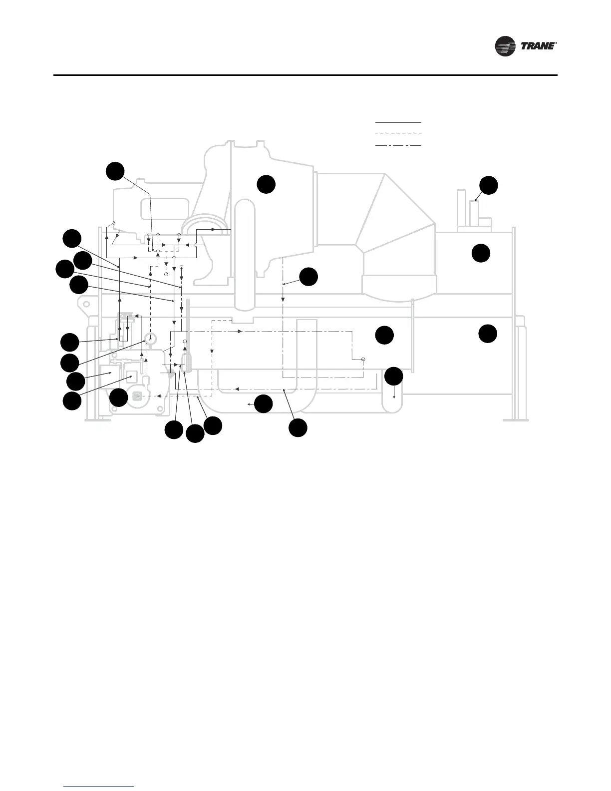
Figure 38. Oil refrigerant pump
1. Motor coolant return to condenser,
53.975 mm (2.125 in.) OD
12. Oil supply to bearings, 22.225 mm (0.875 in.) OD
2. Oil tank vent line, 53.975 mm (2.125 in.) OD 13. Purge
3. Vent line actuated ball valve 14. Compressor
4. Condenser 15. Liquid refrigerant motor coolant supply,
28.575 mm (1.125 in.) OD
5. High pressure condenser gas to drive oil reclaim
eductors, 9.525 mm (0.375 in.) OD
16. Liquid refrigerant to economizer
6. Oil return to tank 17. Liquid refrigerant to evaporator
7. Oil tank 18. Evaporator
8. Oil cooler braze plate heat exchanger 19. Oil reclaim from suction cover (1
st
eductor),
6.35 mm (0.25 in.) OD
9. Oil reclaim from evaporator (2
nd
eductor),
6.35 mm (0.25 in.) OD
20. Motor coolant filter
10. Liquid refrigerant to pump, 41.275 mm (1.625 in.) OD 21. Oil tank junction box enclosure
11. Economizer 22. Oil pump motor terminal box
Compressor lubrication system
Motor cooling system
Oil reclaim system
2
1
3
4
5
6
7
8
9
10
11
17
18
19
12
13
20
14
16
15
22
21