Power Supply Wiring
52 CVHH-SVX001A-EN
• When installing the power supply conduit, ensure that
the position of the conduit does not interfere with the
serviceability of any of the unit components, or with
structural members and equipment. Ensure that the
conduit is long enough to simplify any servicing that
may be necessary in the future (e.g., starter).
• Electrical wire torque specifications—follow starter
manufacturer’s torque specifications.
Circuit Breakers and Fused
Disconnects
Any field supplied circuit breaker or fused disconnect
installed in power supplied to the chiller must be sized in
compliance with NEC or local guidelines.
CE for Control Power Transformer (CPTR)
Option
Important: For the CPTR (Control Power Transformer)
option, chiller mounted/UPS power, the
customer needs to ensure that the supply is
NOT taken from public low voltage
supplies, and that a dedicated clean source
of private power supply is used for chiller
mounted CPTR option when a CE chiller is
selected. This also includes when CPTR
option is standard such as in customer-
supplied starters and remote-mounted
medium voltage AFDs.
All customer wiring, including power wiring to starters/
drives/CPTR Option/UPS shore power, needs to be
separated: 24–27 Vdc, 110–120 Vac, and 380–600 Vac each
need to be in separate conduit runs.
For 110/120 V customer wiring, including main power
supply to CPTR option, it is required that the customer
provides some sort of surge protection ahead of it, and all
customer wiring needs to be run in flexible metal conduit
and grounded at both ends. Any ethernet cables being
used by customer to interface with the Trane chiller must
be shielded ethernet cabling.
The customer is required to provide an overcurrent device
upstream of the CPTR option in accordance with IEC
standards and/or any applicable local and national codes.
The customer is required to follow all local, national, and/
or IEC codes for installation.
Service personnel must use proper PPE for servicing and
should also use proper lockout/tagout procedures during
servicing. The customer should also disconnect the main
supply disconnecting device upstream of the starter or
drive first before performing any service on any part of the
chiller, including the CPTR option, related controls, and oil
pump motor circuits. In addition, service personnel should
first disconnect the supply disconnecting device upstream
of the CPTR option before performing any service on the
CPTR option or its related circuits. Lock the CPTR option
enclosure panel disconnect handle before servicing to
prevent accidental pulling of the disconnect handle.
CE for Starter or Drive
Important:
• All Trane-supplied remote starters and drives used in
conjunction with CVHH or CDHH Trane chillers will be
CE-compliant per EU directives and IEC standards to
which the CVHH and CDHH chillers also comply. All
Trane-supplied remote starters and drives must be
used with CVHH or CDHH Trane chillers to ensure CE
compliance.
• For remote starters and drives: Basic details are
provided on remote starter/drive nameplate. Please
refer to the chiller unit nameplate located on the chiller
mounted control panel for details on wire sizing
(minimum current ampacity) and overcurrent
protection sizing upstream of the unit (maximum
overcurrent protection).
• Always refer to as-built schematic wiring diagrams and
the chiller Installation, Operation, and Maintenance
manual located inside the chiller mounted control
panel (regardless of unit or remote-mounted starter or
drive) for details on wiring, safety, installation, and
warnings.
• Refer to drive-specific Installation, Operation, and
Maintenance manuals for drive and option installation
specifics for unit- and remote-mounted adaptive
frequency drives.
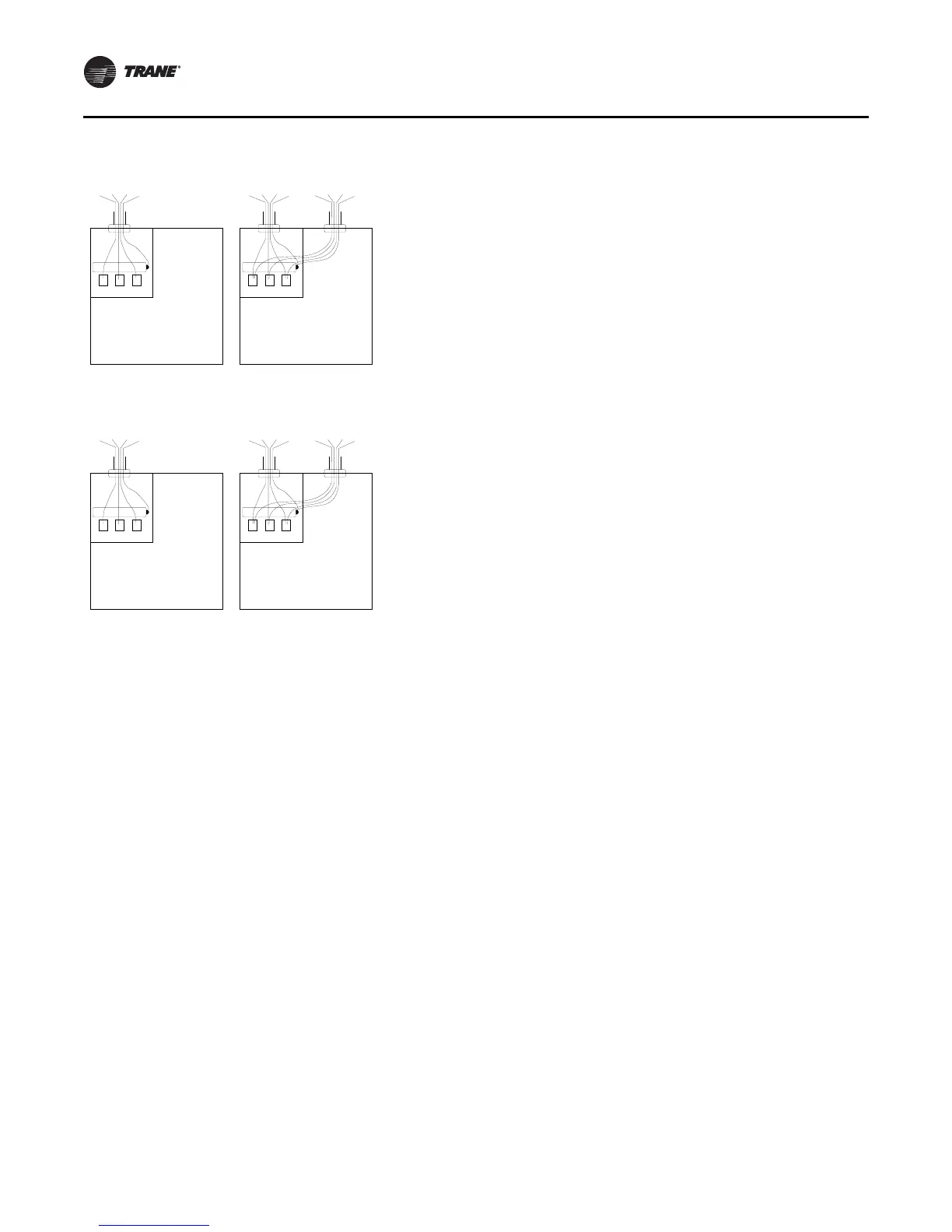
Unit-Mounted Starters
Remote-Mounted Starters
L3
G
L2 L1 L3
G
L2 L1
L3 L2 L1 G L3 L2 L1 G L3 L2 L1 G
L2
L3
G
L2L1 L3
G
L2L1
L3L1 G L3L2L1 G L3L2L1 G