System Control Circuit Wiring (Field Wiring)
CVHH-SVX001A-EN 65
1. With factory-installed ifm efector flow-sensing
devices, a secondary field-provided flow-sensing
device is optional. When a secondary flow-sensing
device is used, remove the factory jumper, and install
its contacts between 1X1-5 to 1K27-4; this places the
secondary flow sensing device in series with the
ifm efector.
2. For field-provided primary proof of flow devices,
connect the primary proof of flow device between
terminals 1X1-6 to 1K16-J2-2. The secondary field
provided flow sensing device is optional; however,
when it is present, it m ust be field-wired in series with
the primary proof of flow device.
Temperature Sensor Circuits
All temperature sensors are factory installed except the
optional outdoor air temperature sensor (refer to
Figure 33, p. 65 for sensor locations). This sensor is
required for the outdoor air temperature type of chilled
water reset. Use the following guidelines to locate and
mount the outdoor air temperature sensor. Mount the
sensor probe where needed, however, mount the sensor
module in the control panel.
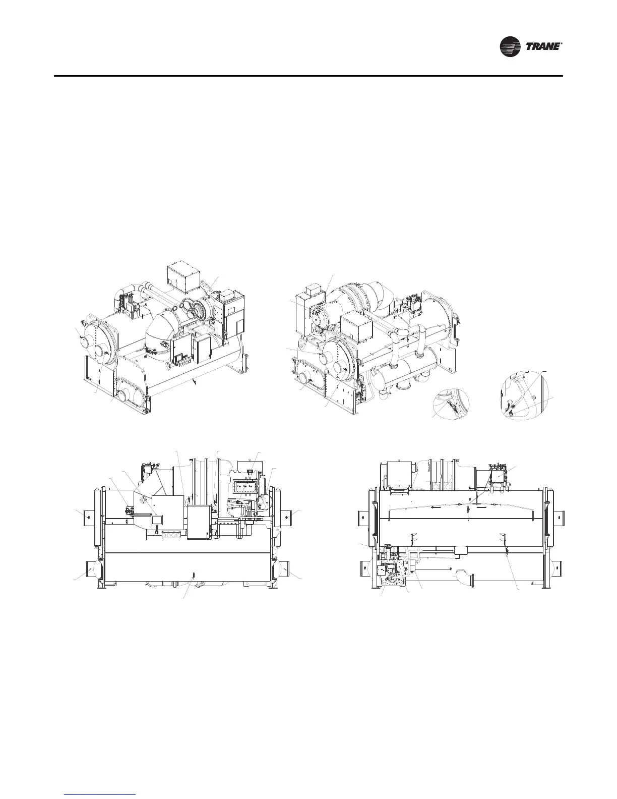
Figure 33. CVHH sensor locations
1 . Tracer AdaptiView display module
2 . Motor winding temperature 1
3 . Motor winding temperature 2
4 . Motor winding temperature 3
5 . Oil pump discharge pressure transducer
6 . Oil tank pressure transducer
7 . Evaporator water differential pressure transducer
8 . Condenser water differential pressure transducer
9 . Compressor discharge refrigerant temperature sensor
1 0 .Evaporator saturated refrigerant temperature sensor
1 1 .Condenser saturated refrigerant tem perature sensor
1 2 .Second condenser entering water temperature sensor (used on HTRC)
1 3 .Second condenser leaving water temperature sensor (used on HTRC)
1 4 .Oil tank temperature sensor
1 5 .Evaporator entering water temperature sensor
1 6 .Evaporator leaving water temperature sensor
1 7 .Condenser entering water temperature sensor
1 8 .Condenser leaving water temperature sensor
1 9 .I nboard bearing temperature sensor
2 0 .Outboard bearing temperature sensor
2 1 .Oil cooling solenoid valve
2 2 .I nlet guide vane first stage actuator
2 3 .I nlet guide vane second stage actuator
2 4 .Outboard bearing pad temperature sensor 1
2 5 .Outboard bearing pad temperature sensor 2
2 6 .Outboard bearing pad temperature sensor 3
2 7 .Condenser high pressure cut out switch
2 8 .Condenser refrigerant pressure transducer
2 9 .Oil tank vent line valve
2
=
4
0
p
1
3
9
7
w
q
5
ty
er
ty
ty
er
er
8
]
a
\
See Detail A
See Detail B
Detail A
Detail B
ty
er
=q
[
u
o
f
6
sd
-
i