Installation: Water Piping
CVHH-SVX001A-EN 27
Three-pass waterboxes have lifting lugs on the top and
bottom. When reinstalling, ensure that the waterbox is
oriented the same way it as removed.
Grooved Pipe Coupling
A customer-supplied, standard flexible grooved pipe
coupling (Victaulic Style 77 or equivalent) should be used
to complete the Victaulic connection for both 1034.2 kPag
or 150 psig and 2068.4 kPag or 300 psig waterboxes.
When a flexible coupling such as this is installed at the
waterbox connections, other flexible piping connectors
(i.e., braided-steel, elastomeric arch, etc.) are usually not
required to attenuate vibration and/or prevent stress on
the connections.
• Refer to the coupling manufacturer’s guidelines for
specific information concerning proper piping system
design and construction methods for grooved water
piping systems.
• Flexible coupling gaskets require proper lubrication
before installation to provide a good seal. Refer to the
coupling manufacturer’s guidelines for proper
lubricant type and application.
Flange-Connection Adapters
When flat-face flange connections are specified, flange-to-
groove adapters are provided (Victaulic Style 741 for
1034.2 kPag or 150 psig systems; Style 743 for 2068.4 kPag
or 300 psig systems). The adapters are shipped bolted to
one of the chiller end-supports. Adapter descriptions are
given in
Tab le 6, p . 28 and Tab le 7, p. 28. The flange
adapters provide a direct, rigid connection of flanged
components to the grooved-pipe chiller waterbox
connections.
In this case, the use of flexible type connectors (i.e.,
braided steel, elastomeric arch, etc.) are recommended to
attenuate vibration and prevent stress at the waterbox
connections. Flange adapters are not provided for CVHH
units with 2068.4 kPa or 300 psig waterboxes that have
356 mm (14 in.) and larger piping connections.
All flange-to-flange assembly bolts must be provided by
the installer. Bolt sizes and number required are given in
Table 6, p. 28 and Table 7, p. 28. The four draw-bolts
needed for the 355.6 mm (14 in.) and larger Style 741
(1034.2 kPag or 150 psig) adapters are provided. The
Style 741, 1034.2 kPag or 150 psig flange adapter requires
a smooth, hard surface for a good seal.
Connection to other type flange faces (i.e., raised, serrated,
rubber, etc.) will require the use of a flange washer
between the faces. Refer to the flange adapter
manufacturer’s guidelines for specific information.
The Style 743 (2068.4 kPa or 300 psig) flange adapters are
designed to mate with raised-face flanges. They can be
used with flat-faced flanges; however, only if the raised
projections on the outside face of the adapter are
removed; see
Figure 17. The flange-adapter gasket must
be placed with the color-coded lip on the pipe and the other
lip facing the mating flange.
Table 5. Water piping connection components
Customer Piping Connection
Uni t Model
Unit Connection
Type Victaulic Flanged
CVHH
Fl an g ed (Co nd e n ser
032–050 150 psig
[ 1034.2 kPag] non-
marine only)
Customer
provided
Victaulic coupling
No adapter
required
CVHH Victaulic (All others)
Trane provided
Victaulic-to-
flange adapter
Figure 15. Customer piping connection types
Water Box
Flange Adaptor
Trane Provided
Flanged
Waterbox
Flange Adaptor
Tr an e pr ov i d ed
Water Box
Style 77 Flexible
Customer Provided
Customer
Victaulic
Wat erbox
Style 77 Flexible
Customer provided
Customer
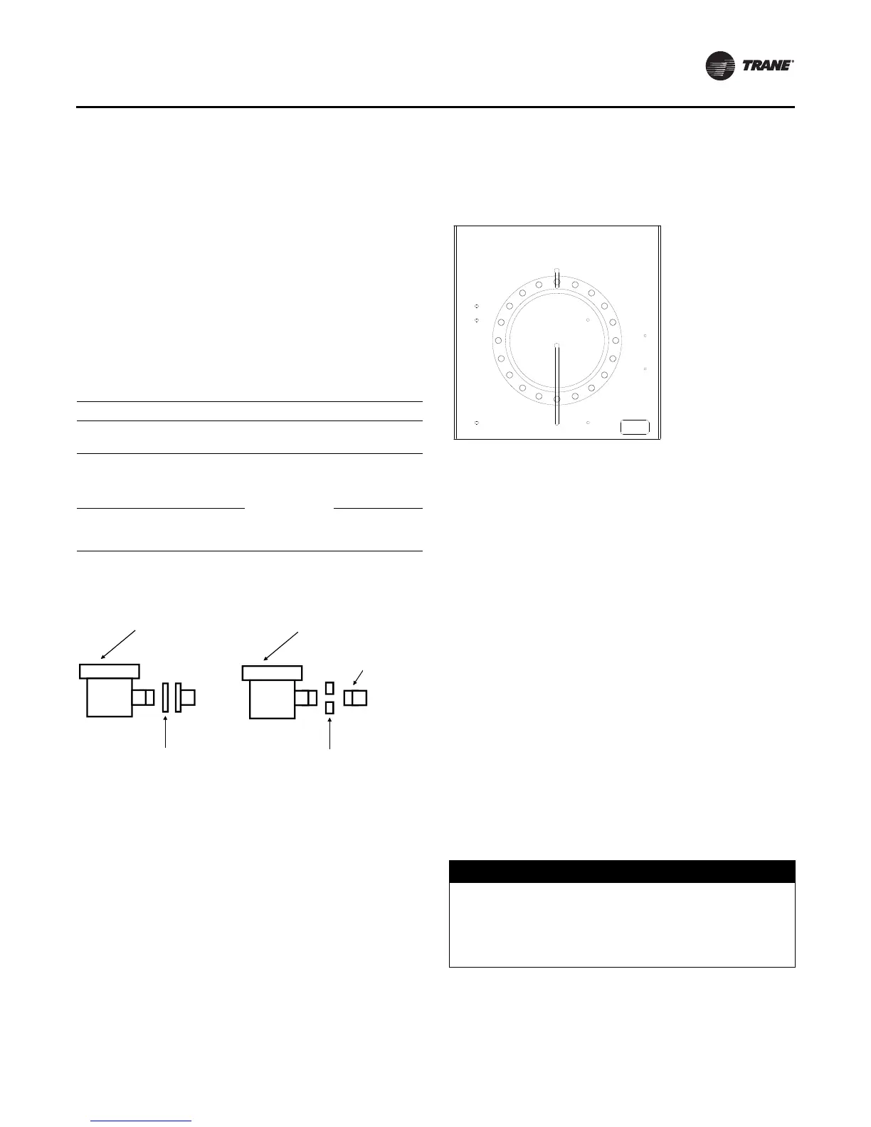
Figure 16. Typical shipping location for flange
NOTICE:
Piping Connection Leaks!
Failure to provide effective seal could result in
equipment or property-only damage. To provide
effective seal, gasket contact surfaces of adapter must
be free of gouges, undulations or deformities.