Power Supply Wiring
CVHH-SVX001A-EN 53
• Customers are responsible for all field wiring with
respect to EMC and EMI interference. Customers are
responsible to mitigate the risks associated with EMC
and EMI interference that can occur as a result of
customer-provided field wiring as dictated by
international, national, and local codes. This also
implies that for remote-mounted starters and drives,
customers are responsible for the entire field wiring
into the starter/drive as well as between the starter/
drive and the chiller/compressor terminals with
respect to EMC and EMI interference. It also implies
that customers are responsible for incoming power
wiring to both the starter/drive and CPTR option
enclosure unit-mounted panel with respect to EMC
and EMI interference.
All customer wiring, including power wiring to starters/
drives/CPTR Option/UPS shore power, needs to be
separated: 24–27 Vdc, 110–120 Vac, and 380–600 Vac each
need to be in separate conduit runs.
For 110/120V customer wiring, including power supply to
CPTR option, it is required that the customer provides
some sort of surge protection and all customer wiring
needs to be run in flexible metal conduit and grounded at
both ends.
For remote starters interfacing with the Trane chiller, all
wiring needs to be run in flexible metal conduit and
grounded at both ends. Any ethernet cables being used by
customer to interface with the Trane chiller must be
shielded ethernet cabling.
The customer is required to provide an overcurrent
protective device upstream of all starters and drives in
accordance with IEC standards and/or any applicable local
and national codes.
Service personnel must use proper PPE for servicing and
should also use proper lockout/tagout procedures during
servicing: lock the starter disconnect handle before
servicing to prevent accidental pulling of disconnect
handle at the starter panel. In addition, service personnel
should first disconnect the main supply disconnecting
device upstream of the starter or drive before performing
any service on any part of the chiller.
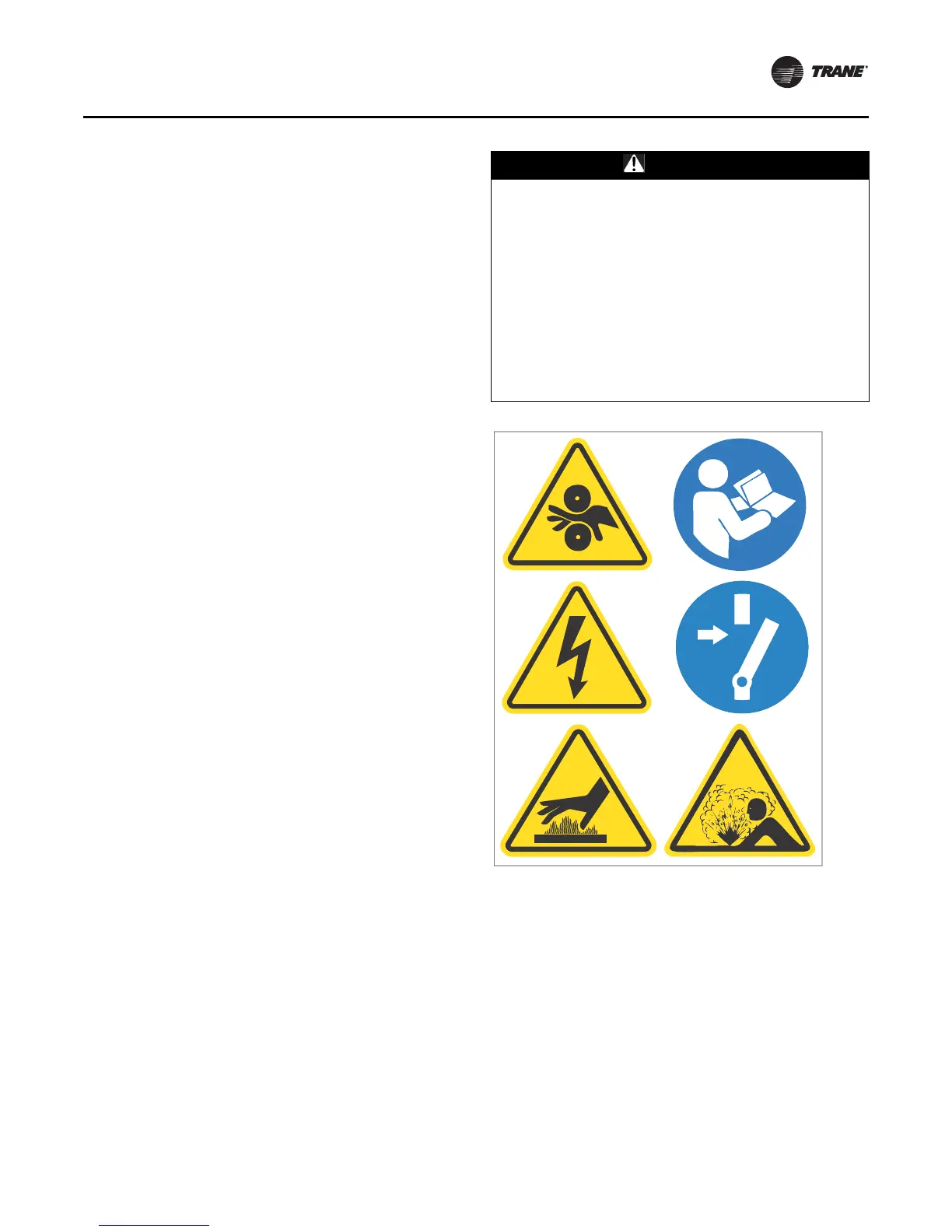
Note: Graphic labels (shown above) are used for CE
application only.
Important:
• Before servicing, disconnect all power sources and
allow at least 30 minutes for capacitors to discharge.
• All electrical enclosures—unit or remote—are IP2X.
For CE units, the convenience outlet in the control panel
requires a suitable adaptor to m eet the needs of customers
with different plug requirements.
WARNING
Lockout/Tagout Before Removing Touch-
Safe Covers!
Failure to follow instructions regarding touch-safe
covers could result in death or serious injury. Touch-safe
covers inside panels are there for protection and may
be removed if necessary for service only and only after
disconnection of main power supply. Before removing
any touch-safe cover, ensure that there is no line power
first. Removal of touch-safe covers would be at the
customer/ service personnel’s own risk. After any
service is completed, if the touch-safe covers have been
removed, the touch-safe covers need to be put back in
to ensure safety and protection.