Vent Piping
CVHH-SVX001A-EN 35
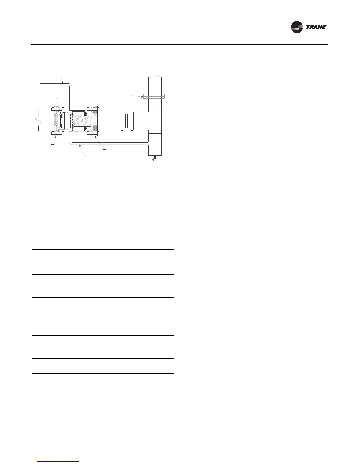
Connect the discharge of the valve assembly to the vent
line connected to the outdoors.
Note: Make sure there are no crosses
1
, elbows, tees
or any other obstructions within the first
22.86 cm (9 in.) of valve discharge. Refer to
ASHRAE Standard 15, national, state, and local
codes for additional requirements on piping
rupture disk and relief valve vent lines.
Figure 22. External vent line and drip leg (not provided)
1
A derate on the rated flow capacity for this configuration is published in RuptureGuard engineering bulletin, E/CTV-EB-10.
Table 8. “C” values used to determine rupture disk vent
line sizes (kg/s); for use with
Figure 23, p. 36
NTON
Evap.
Size
( EVSZ)
Cond.
Size
( CDSZ)
“C” Values for Unit Com ponents
Total
“C”
Value Evap. Cond. Econ.
Oil
Tank
900–1200 100M 100M 0.853 0.368 0.310 0.141 0.034
900–1200 100L 100L 0.939 0.415 0.349 0.141 0.034
900–1200 130M 130M 0.932 0.412 0.346 0.141 0.034
900–1200 160M 200M 1.022 0.461 0.386 0.141 0.034
900–1200 200L 220L 1.222 0.575 0.473 0.141 0.034
900–1200 220L 220L 1.284 0.637 0.473 0.141 0.034
1500-1700 200L 200L 1.195 0.575 0.435 0.151 0.034
1500-1700 220L 220L 1.295 0.637 0.473 0.151 0.034
900–1200 100M 10HM 0.967 0.368 0.424 0.141 0.034
900–1200 130M 13HM 1.053 0.412 0.467 0.141 0.034
900–1200 160M 20HM 1.144 0.461 0.509 0.141 0.034
1500-1700 200L 20HL 1.332 0.575 0.573 0.151 0.034
1500-1700 220L 22HL 1.458 0.637 0.637 0.151 0.034
Notes:
1 . Rupture disk diam eter is 76.2 mm (3 in.).
2 . Use the total “C” value in
Figure 23, p. 36 to determine the vent line
pipe diameter.
3 . If piping m ultiple rupture disks (multiple units) to a comm on vent
line, first determine the total “C” value for each unit, and then; add
all “C” values together and apply the result to
Figure 23, p. 36.
4 . The CVHH unit is a Sim plex chiller and has (1) refrigerant circuit and
(1) relief device.
Purge
Exhaust
Flange
Drain Valve
Drain Line
Rupture
Disk
Inlet
Flange
Outlet Flange