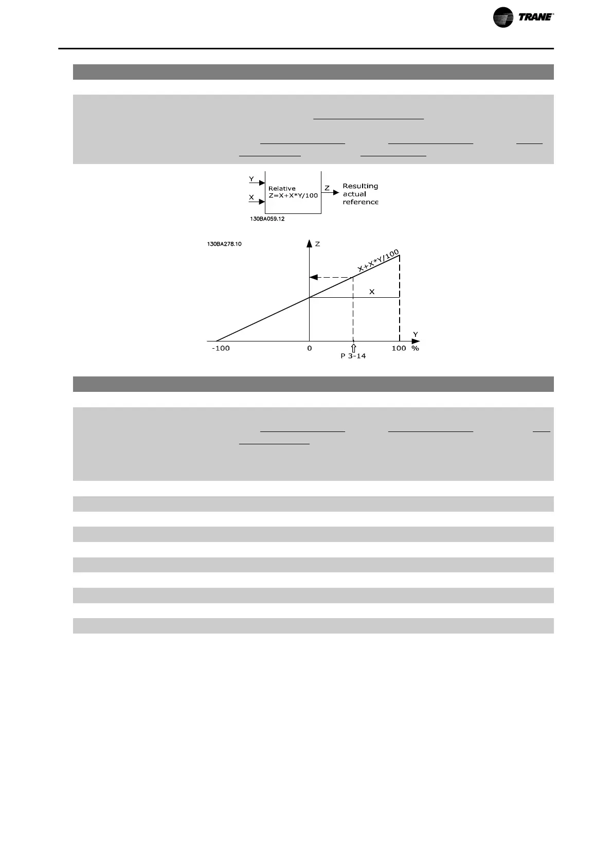
3-14 Preset Relative Reference
Range: Function:
0.00 %* [-100.00 - 100.00 %] The actual reference, X, is increased or decreased with the percentage
Y, set in par.3-14
Preset Relative Reference. This results in the actual ref-
erence Z. Actual reference (X) is the sum of the inputs selected in par.
3-15
Reference 1 Source, par.3-16 Reference 2 Source, par.3-17 Refer-
ence 3 Source and par.8-02 Control Source.
3-15 Reference 1 Source
Option: Function:
Select the reference input to be used for the first reference signal. par.
3-15
Reference 1 Source, par.3-16 Reference 2 Source and par.3-17 Ref-
erence 3 Source define up to three different reference signals. The sum
of these reference signals defines the actual reference.
This parameter cannot be adjusted while the motor is running.
[0] No function
[1] * Analog input 53
[2] Analog input 54
[7] Pulse input 29
[8] Pulse input 33
[20] Digital pot.meter
[21] Analog input X30/11
[22] Analog input X30/12
[30] Ext. Closed Loop 1
[31] Ext. Closed Loop 2
[32] Ext. Closed Loop 3
Parameter Description
TR200 Programming Guide 75

 Loading...


