24 Tracer AdaptiView Display Operations Guide • CTV-SVU01B-EN
Reports
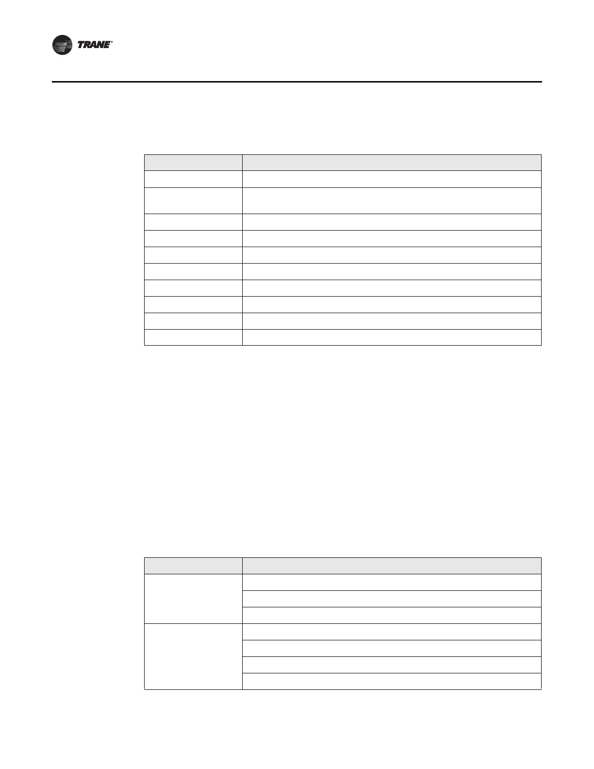
A description of top-level operating modes is given in Ta bl e 5.
Submodes are dependent on the top-level mode. Their appearance on the Chiller
Operating Modes screen has the following characteristics:
• The newest submode appears at the top of the submode list.
• Submodes disappear when they no longer apply.
• The screen displays up to 6 submodes.
• If less than 6 submodes are active, the submode rows that do not apply are blank.
Tab l e 6 shows each top-level mode in the left column with corresponding submodes in
the right column.
Note: “MIN:SEC” refers to a count-down timer that appears on the screen to indicate
how long the submode will remain active. “IGV Position %” refers to a value that
indicates the position of the inlet guide vane (IGV).
Table 5. Chiller top-level operating modes
Top-level mode Description
Stopped Unit is inhibited from running and will require user action to go to Auto.
Run Inhibit Unit is inhibited from running by building automation system (BAS), external
control source (Ext), or Auto Reset diagnostic
Auto Unit is determining if there is a need to run.
Waiting to Start Unit is waiting for tasks required prior to compressor start to be completed.
Starting Compressor Unit is starting compressor.
Running Compressor is running with no limits in effect.
Running—Limit Compressor in running with limits in effect.
Preparing to Shutdown Unit is closing inlet guide vanes prior to compressor shutdown.
Shutting Down Compressor has been stopped and unit is performing shutdown tasks.
Free Cooling Unit is in Free Cooling mode and will not run the compressor.
Table 6. Chiller submodes
Top-level mode Corresponding sub-level mode
Stopped Local Stop
Panic Stop
Diagnostic Shutdown—Manual Reset
Run Inhibit Ice Building Is Complete
Tracer In hibi t
External Source Inhibit
Diagnostic Shutdown—Auto Reset
 Loading...


