- 7 - MODEL 3587
3. Operation
3.1 Power supply
First confirm the power OFF of the switch located at the rear panel of the instrument and
connect cord to the power supply. Then, ON the power supply switch. This instrument
becomes in operation condition immediately but it is preferred for preheating 30 minute
before the use.
As this instrument is equipped with a parameter holding function, following (1) to (4)
status can be memorized even though the power supply is turned OFF.
(1)10 sets of memories (Measurement voltage, Resistance range, Comparator
setting, Measurement condition of timer etc.)
(2)Key lock state
(3)Start input setting (REMOTE/MANUAL)
(4)Various types of setting
3.2 Connection of test leads
! Caution
This tester comes under the measurement category 0. Do not use the tester for the
measurement of the circuit having measurement category of Ⅱ, Ⅲ and Ⅳ.
For the safety, please use the test lead prescribed by maker only.
If the HIGH terminal is short circuited to the ground, the LOW terminal becomes high
voltage, which is very dangerous.
Do not touch the testing lead by hand during the measurement.
It may cause electric shock during connection and disconnection of testing leads. Turn
OFF the power supply to instrument.
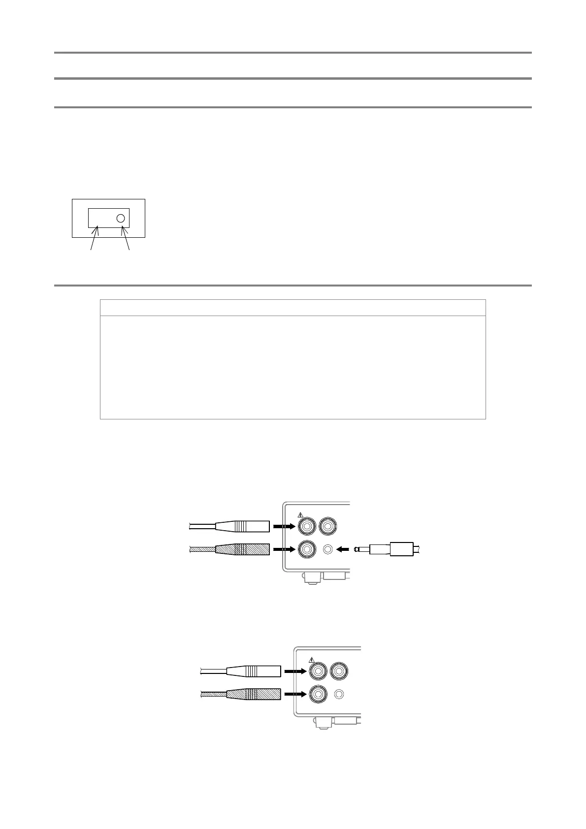
3.2.1 Probe with switch (Model name 5813-23:Option)
Remote measurement operation is performed with the switch built in probe.
Insert the red plug of the probe with switch to the HIGH terminal (red), the remote plug
to the REMOTE terminal, and the black cable to the LOW terminal (black) respectively.
3.2.2 HIGH probe (Model name5813-22:Option), LOW probe (Model name5813-21:Option)
Insert HIGH probe into HIGH terminal (red) and LOW probe into LOW terminal (black)
respectively.
-
ON
OFF
LOW
REMOTE
GUARD
HIGH
Red
Black
LOW
REMOTE
GUARD
HIGH
Red
Black