- 5 - MODEL 3587
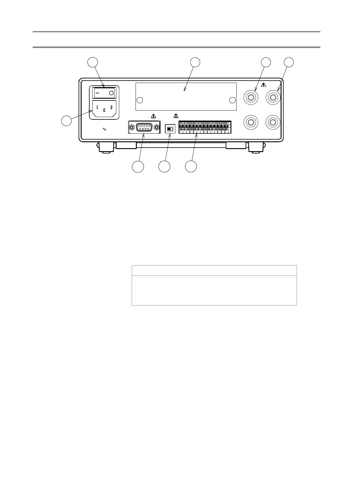
2.2 Rear panel
⑨Power supply switch
Power supply ON/OFF switch
⑩Power inlet
Connect the supplied power supply cord. Use the power supply voltage and
frequency within the specified range.
⑪Rear measuring
terminal
HIGH:+Measuring terminal When the sample to be measured is ground, it is to be
connected to the grounded side of the sample.
LOW:-Measuring terminal To be connected to the non-grounded side of the
sample.
! Caution
If the HIGH terminal is short circuited to the ground, the
LOW terminal becomes high voltage, which is very dangerous.
Do not touch the measuring terminal during the measurement
(TEST lights up).
⑫Connection check
terminal
Terminal for checking the contact status of the contact probe.
⑬RS-232C connecter
Connector for RS-232C communication
⑭P/N Selector switch
Switch to select the external control and BCD output of sink (NPN) and source
(PNP)
⑮Input and output
terminal
Terminals for external control
⑯Interface board mounting part
For BCD Interface board Installation part
100-240V 50-60Hz
AC LINE 28VA MAX
O-COM
GO
LO
HI
CHG
C-ERR
TEST
I-COM
MEM1
MEM2
MEM4
MEM8
START
RESET
CONTROL
PN
RS-232C
LOW
HIGH
L CONTACT
H CONTACT
9
10
13
14
15
16 12 11