11
zero point, and the trajectory of the robotic arm refers to the tool coordinate
system.
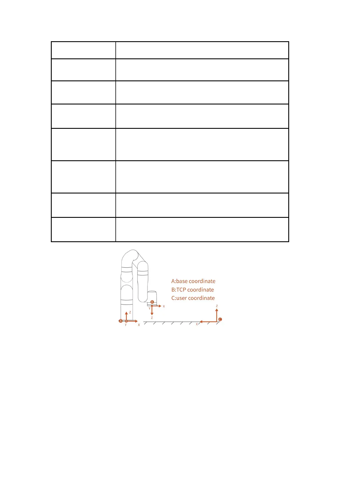
User Coordinate System
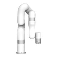
(please refer to the figure 1)
The user coordinate system can be defined as any other reference coordinate
system rather than the robot base.
In this mode, the robotic arm will enter the ‘zero gravity’ mode, since the
gravity is compensated, the user can guide the robotic arm position directly by
hand.
Teach sensitivity range is from 1 to 5 level. The larger the set value, the higher
the teach sensitivity level, and the less the force required to drag the joint in the
manual mode.
The collision sensitivity range is from 0 to 5 level. When it is set to 0, it means
that collision detection is not enabled. The larger the set value, the higher the
collision sensitivity level, and the smaller the force required to trigger the
collision protection response of the robotic arm.
General-purpose input and output.
For the input, you can check the potential of the pin by reading a register;
For the output, you can write a certain register to make this pin output high or
low potential;
When this mode is activated, the boundary range of the cartesian space of the
robotic arm can be limited. If the tool center point (TCP) exceeds the set safety
boundary, the robotic arm will stop moving.
When this mode is activated, the maximum linear velocity of the Cartesian
motion of the robotic arm, the maximum joint speed, and the range of the joint
motion will be limited.
Figure 1
xArm Motion Parameters
The parameters of the robotic arm are shown in Table 1.1 and Table 1.2.