45
2.4.3. General Digital I/O Function
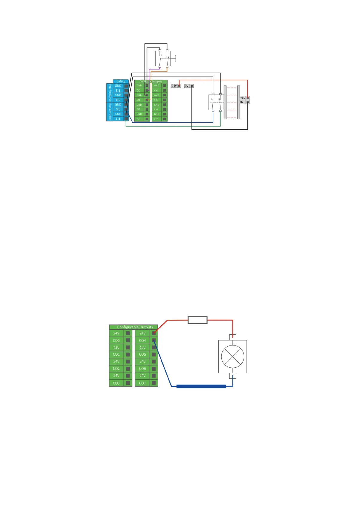
2.4.3.1. Configurable Digital Output
The digital output is implemented in the form of NPN. When the digital output is
enabled, the corresponding connector will be driven to GND. When the digital output
is disabled, the corresponding connector will be open (OC/OD).
Users must follow the electrical specifications set in section 2.4.1 ‘universal
specification’.
The following example shows how to use the digital output, as the internal output is
an open-drain(OD) output, so you need to connect the resistor to the power supply
according to the load. The resistance and power of the resistor depend on the specific
use.
Note: It is highly recommended to use a protection diode for inductive loads as shown
below.