EasyManuals Logo

UFactory xArm 5 User Manual

UFactory xArm 5
182 pages
To Next Page IconTo Next Page
To Previous Page IconTo Previous Page
Page #36 background imageLoading...
Page #36 background image
36
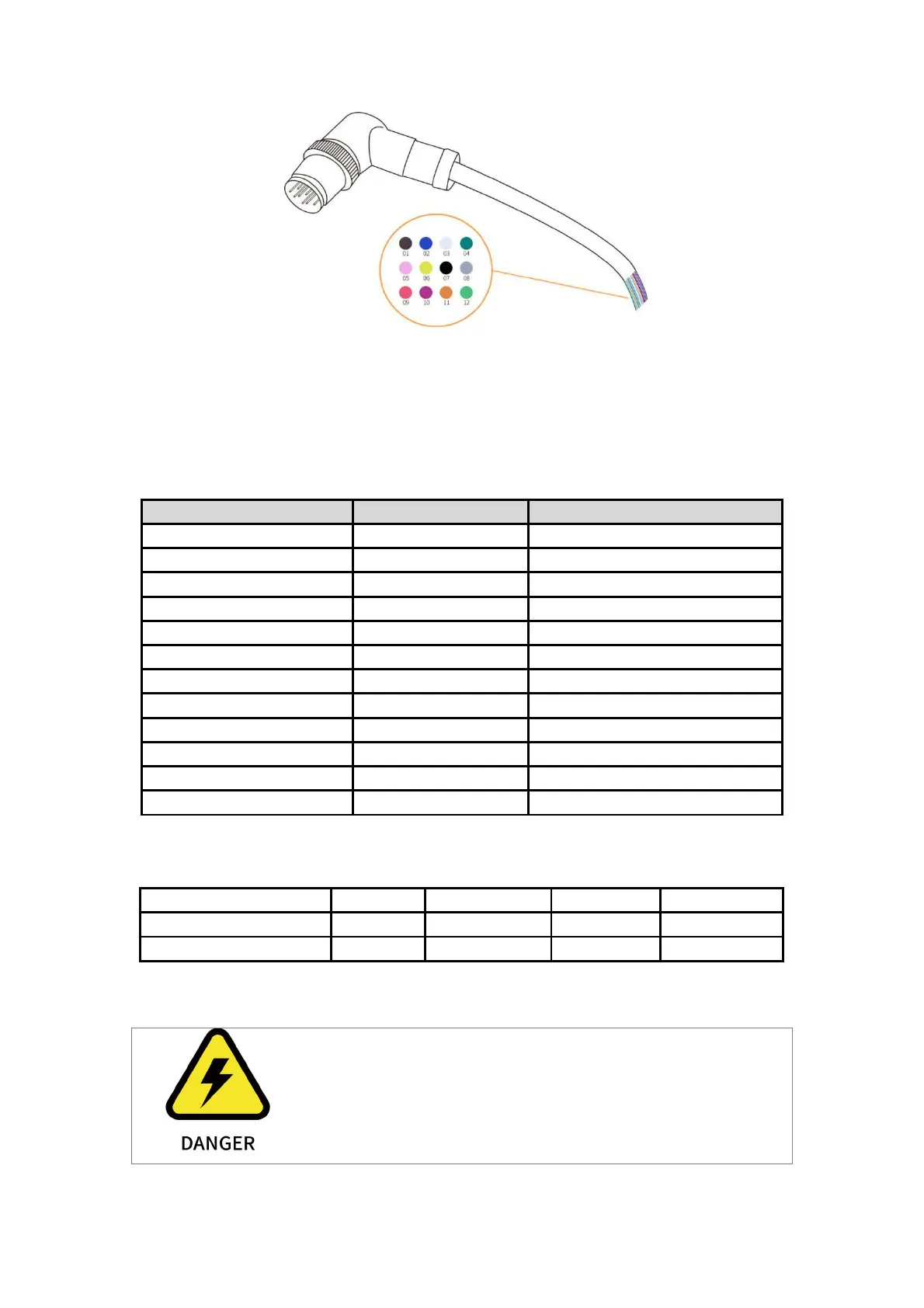
There are 12 pins inside the cable with different colors, each color represents different
functions, please refer to the following table:
Pin sequence
Color
Signal
1
Brown
+24VPower
2
Blue
+24VPower
3
White
0V (GND)
4
Green
0V (GND)
5
Pink
User 485-A
6
Yellow
User 485-B
7
Black
Tool Output 0 TO0
8
Grey
Tool Output 1 TO1
9
Red
Tool Input 0 TI0
10
Purple
Tool Input 1 TI1
11
Orange
Analog input 0 (AI0)
12
Light Green
Analog input 1 (AI1)
The electrical specifications are as follows:
Parameter
Min. Value
Typical Value
Max. Value
Unit
Supply Voltage in 24V Mode
-
24
30
V
Supply Current *
-
-
1800
mA
Note: * It is strongly recommended to use a protection diode for inductive loads.
Make sure that the connecting tool and the gripper do not
cause any danger when the power is cut, such as dropping of
the work-piece from the tool.

Table of Contents

Questions and Answers:

Question and Answer IconNeed help?

Do you have a question about the UFactory xArm 5 and is the answer not in the manual?

UFactory xArm 5 Specifications

General IconGeneral
BrandUFactory
ModelxArm 5
CategoryRobotics
LanguageEnglish

Related product manuals