Section 2. Considerations before Installation
Refer to Figure 1-2 in Section 1 for the dimensions of the compressor.
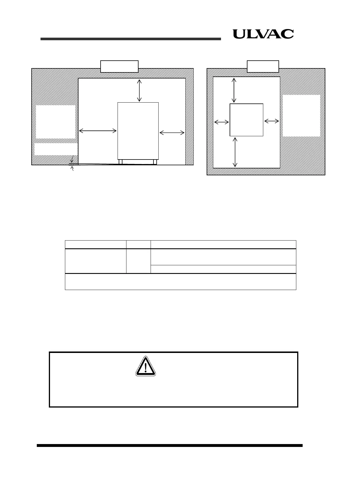
Figure 2-1 Required space for compressor installation (scale: mm) and
levelness
2.2 Wiring requirements
Table 2-1 shows the specifications of optional input power cables. For connecting
procedures of the input power cable refer to “Section 4.6 Electrical connections”.
Table 2-1 Input power cable specifications
Item Symbol
C30HVRT
Input power cable
INPUT
POWER
Copper wire / 600VAC,
3 conductors with ground
(*1)
5.5mm
2
, 8 mm
2 (*2)
(*1)
The color of the ground wire is green.
(*2)
Unless otherwise specified, 5.5 mm
2
cables
are attached to the compressor.
Supply AC power for compressor from the equipment-side distribution panel. The
distribution panel should have branched circuit breakers for each compressor (see Figure
2-2). Circuit breakers must be appropriate and meet the international and the national
codes and standards of the country installed (Refer to UL489 and IEC60947-2). Also,
circuit breakers must be installed in the distance to be able to check the compressor.
Refer to Table 1-2 in section 1 for circuit breaker current rating.
D > 50
H > 300
Compressor
C30HVRT
D > 50
Wall,
C30HVRT, or
other
e
ui
ment
Slope <±5degrees
Front view Top view
D>500
Wall,
C30HVRT, or
other
equipment
D>500
D>50
D>50
Front
CAUTION
In most standards, it is required to install a branch breaker to protect power cables connected
to the equipments. A circuit breaker must be installed. Failure to follow this procedure could
seriously damage the equipment.
2-2
ULVAC CRYOGENICS INCORPORATED