C30HVRT Compressor Unit Instruction Manual
ULVAC CRYOGENICS INCORPORATED 4-1
Section 4 Installation, Piping, and Wiring
4.1
Prior to installation............................................................................... 4-1
4.2 Connecting cooling water piping ......................................................... 4-2
4.3 Connecting and disconnecting helium flexible hoses ......................... 4-2
4.4 Cryocooler connections ...................................................................... 4-4
4.5 Electrical connections ......................................................................... 4-5
4.6 Wire rooting for compressor and other equipments .......................... 4-10
4.1 Prior to installation
This section describes appropriate procedure for installing C30HVRT and connecting the
compressor to a cryocooler.
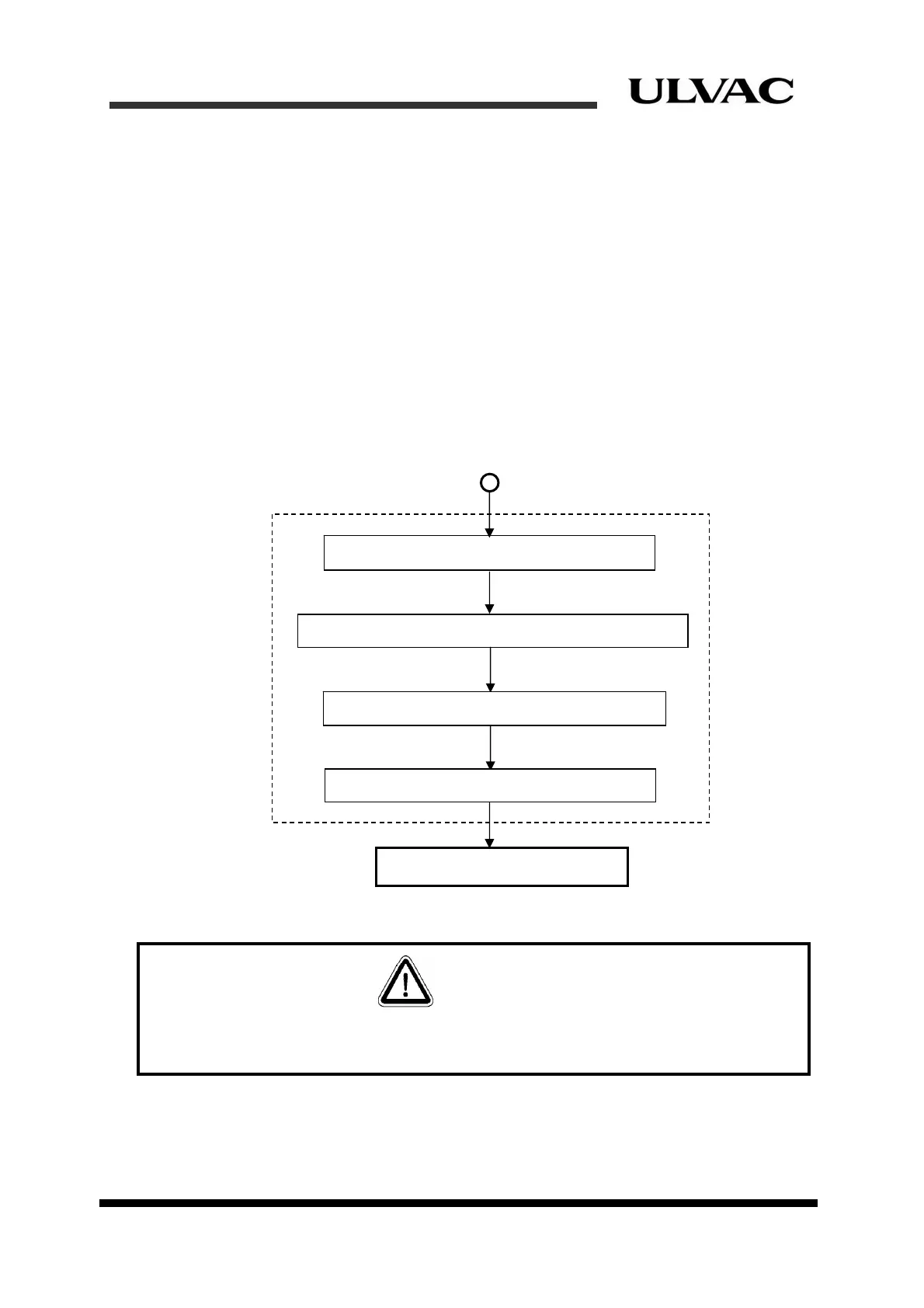
Figure 4-1 is the block diagram for the compressor installation.
Figure 4-1 Installation procedure
Connecting cooling water piping
Connecting flexible hoses
Connecting the compressor to the cryocooler
Making electrical connection
Start operation (see section 5)
To ensure safe, reliable system performance, read this manual as well as other relevant
manuals completely to gain a thorough understanding before beginning work.
CAUTION