Section 4
Installation, Piping, and Wiring
4-8
ULVAC CRYOGENICS INCORPORATED
C30HVRT wiring precautions
(1) In Alternate operating mode, the pins number 15 and 16 should be wired as operation
command signals but not 6, 7, 8 and 9.
Conversely, in Momentary operating mode the pins number 6, 7, 8, and 9 should be
wired as operation command signals but not 15 and 16. Therefore choose
appropriate wiring depending on the operating mode.
(2) Wire GND (pin number 14) only when it is needed. GND has the same electric
potential as the compressor chassis. Connecting ground wire that has different power
line (such as AC400V) from the compressor power supply line may cause overcurrent
or noise problem due to a ground-loop.
(3) Twist each signal line with a nearby COM line. (e.g.: Twist pin number 15 and 16)
(4) COM lines are used as return lines of nearby signal lines. Therefore it is necessary to
wire all the COM line which corresponds to the signal line, not to use just one COM
line.
(5) Twist paired signal lines such as COMP RUN1 and COMP RUN2.
(6) These are signal lines. Do not drive the power device by direct output signals (such
as answer-back signals) from the compressor. It may cause a failure of the product.
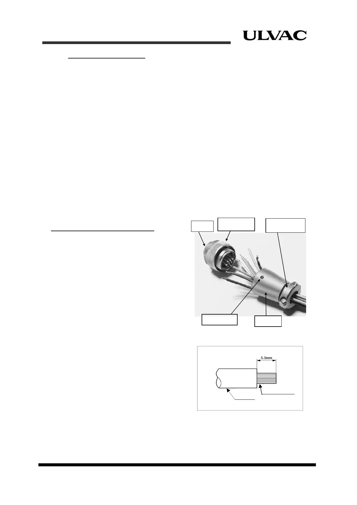
Remote connector wiring procedure
Descriptions of the connector are shown in
Figure 4-9.
(Taking apart a connector)
1. Loosen the set screw for the end bell
fixation counterclockwise, and then take
the end bell off from the connector body
by turning it.
2. Remove the clamp saddle.
Figure 4-9 Connector parts descriptions
(Connecting cables)
3. Peel off the insulating coating to expose the
proper length of the conductor.
(Figure 4-10)
4. Pass the cables through the end bell and
then solder the cables to the connector
pins. Cover the soldered parts with heat
shrinkable tubing.
Coupling nut
Barrel
Set screw
End bell
Clamp saddle
Coating
Conductor
Figure 4-10 Cut length of insulation coating