C30HVRT Compressor Instruction Manual
T S R
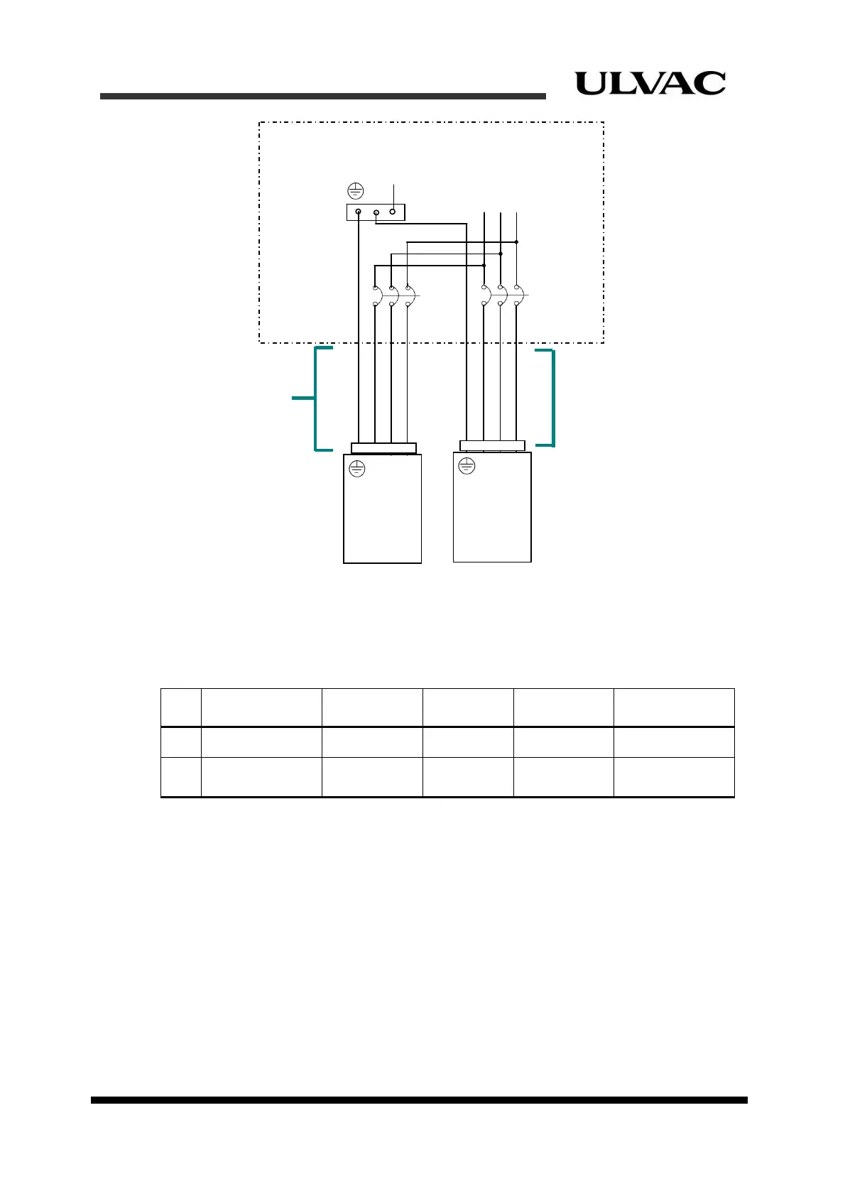
PE
equipment-side distribution panel
C30HVRT compressor X 2
T S R
Table 2-2 shows wire gauges of cryocooler cable and remote cable for use.
Table 2-2 Control and signal wire gauges
No.
Item Symbol
Connection
Type
Wire Size Note
1
Cryocooler cable
NO.1
Connector #20 AWG Option
2
Remote cable
REMOTE
RESPONSE
Connector #22 AWG Customer supply
NOTE: Refer to “Section 4 Equipment Installation, Piping, and Wiring” for routing of
the cables above.
2.3 Cooling water requirements
Cooling water must meet the requirements indicated in the following subsections. It is
necessary to maintain the performance of the compressor for extended periods without
malfunction.
CB1
CB2
AC200/220V 3φ
T S R
Power cable
Figure 2-2 Equipment-side power circuit
ULVAC CRYOGENICS INCORPORATED 2-3