Section 2. Considerations before Installation
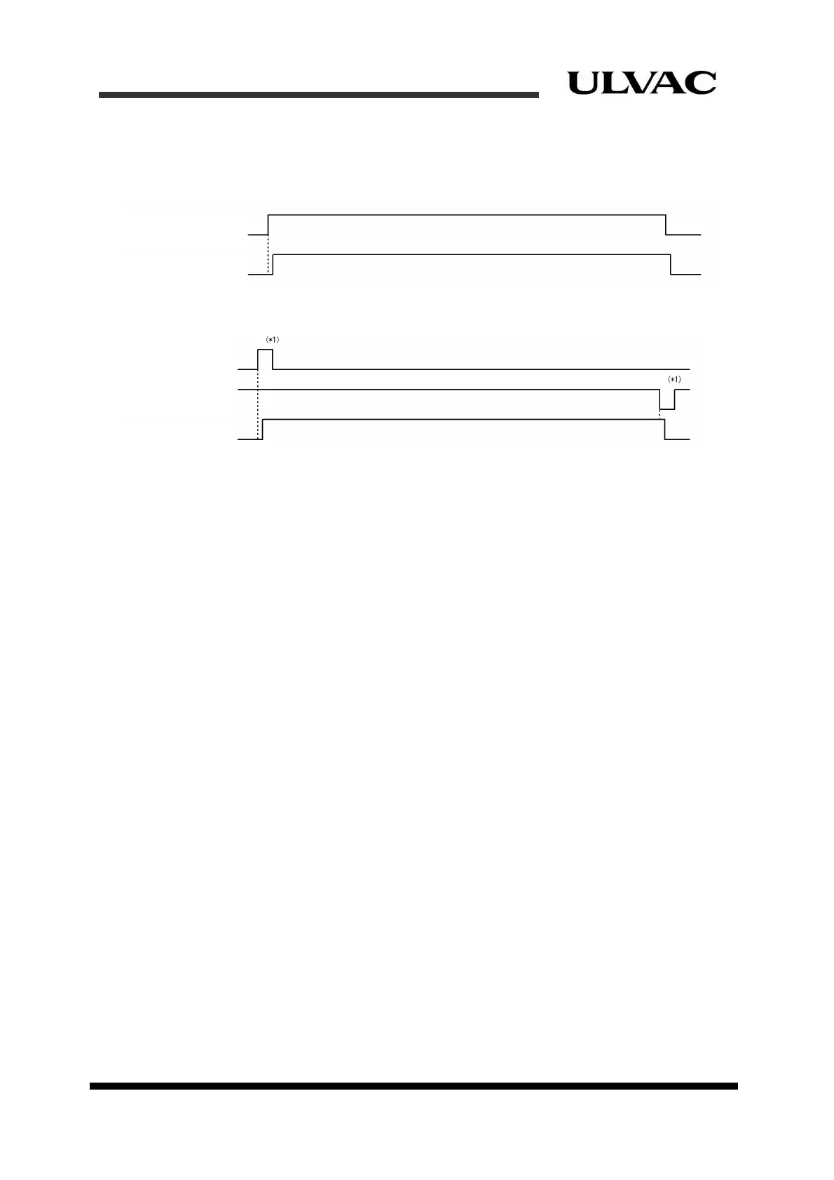
2.5.6 Signal timing charts
Figure 2-6 shows a timing chart for “Alternate operating mode”.
Figure 2-7 shows a timing chart for “Momentary operating mode”.
COMP・CRYOCOOLER
START/STOP
COMP・CRYOCOOLER
ACK
Figure 2-6 Figure 2-6 Timing chart for Alternate operating mode
COMP・CRYOCOOLER
START
COMP・CRYOCOOLER
STOP
COMP・CRYOCOOLER
ACK
*
1) The holding time is 0.3 seconds or more.
Figure 2-7 Timing chart for Momentary operating mode
(Delay and recovery of Answer-back signal)
Please be sure to set the timeout time of an answerback signal as 8 seconds or more. The
reason is explained below.
In normal operation, an answer-back signal is fundamentally send to the equipment side
within a maximum of 0.3 seconds delay in response to a command signal. In the following
conditions, however, the answer-back signal is sent behind time:
(a) When the power supply of the compressor is turned ON
(b) When the reboot command of the compressor is emitted within 0.3 second from the
operation stop command
(c) When a short power interruption for less than 2 seconds has occurred
In case of the above (a), it takes a few seconds for the compressor to initialize after it is
powered on. Therefore the compressor will neither recognize nor output any remote signal
with the equipment for a maximum of 5 seconds. For reference, the signal delay when
powered on in Alternate operating mode is shown in Fig. 2-8.
2-10
ULVAC CRYOGENICS INCORPORATED