Compressor Unit Instruction Manual
ULVAC CRYOGENICS INCORPORATED 1-7
④HELIUM FILL FITTING (Inside the panel)
Use this to adjust helium gas pressure when needed. When adding helium gas, use
only helium gas with purity of 99.999% or above.
Refer to “Section 7.3 Adjusting system helium pressure” for details.
⑤CASTERS
Use them to move the compressor. Lock the casters when not moving the
compressor.
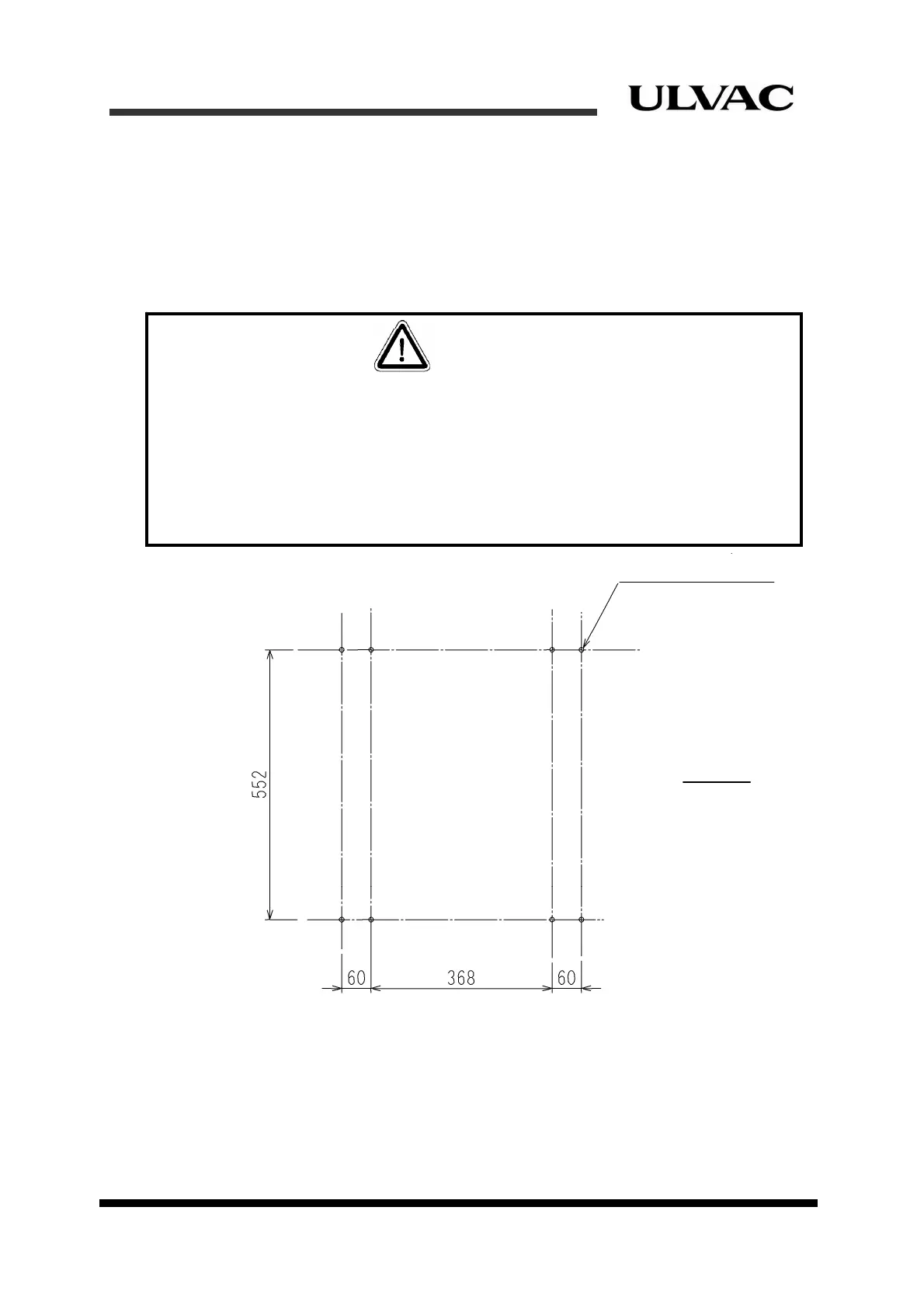
Figure 1-5 Anchor bolts mounting positions (example)
⑥ALARM STATUS TABLE
This shows a list of alarm codes indicated by the STS (Status) LED indicators for alarm
indication. Refer to “Section 8.3 Alarm code descriptions” for troubleshooting procedure
of each alarm code.
All status display LED indicators will remain unlit when there is no problem.
8-M10 anchor volt
Front
All caste f the compressor unit must be locked after the compressor unit has been
placed at a proper position or in storage. This is to avoid injury to persons from an
unexpected slippage of the compressor.
It is also equired to have preventative measures for slippage and/or overturning in case of
earthqua e. Please contact us if fixing brackets need to be attached to the compressor.
Figure 1 shows an example of anchor bolts mounting positions when fixing brackets are
attached to the compressor
CAUTION
rs o
r
k
-5