C30HVRT Compressor Unit Instruction Manual
PIN No.
PIN No.Input Signal
Output Signal
C30HVRT REMOTE/RESPONSE
(SRCN6A25-16P)
1
2
6
7
8
9
10
11
14
15
16
Wire gauge: AWG22 - 18
ALARM1
ALARM2
COMP START
COMP STOP
COM
COM
COMP RUN1
COMP RUN2
(GND)
COMP ON/OFF
COM
12
(Reserved for Factory test)
1
4
5
10
14
16
13
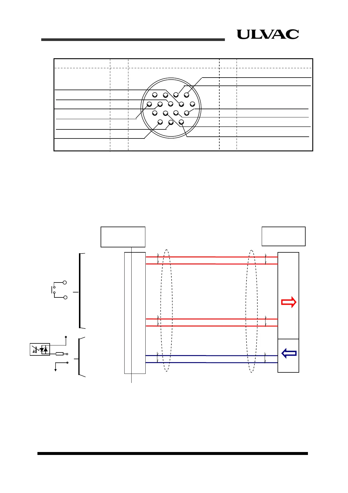
Figure 4-7 Remote connector pin assignments for C30HVRT
(View of from the plug soldering side)
A typical wiring for C30HVRT with a single cryocooler in “Alternate operating mode” is
shown in Figure 4-8. Also, a typical wiring for C30MVR with three cryopumps in
“Momentary operating mode” is shown in Figure 4-11.
Equipment
Interface
1
2
6
7
8
9
10
11
14
15
16
(COMP START)
(COMP STOP)
COMP RUN1
ALARM1
(COM)
(COM)
COMP RUN2
Answer-back
Input etc.
COM
+V
COMP ON/OFF
COM
Command
Output
GND
REMOTE
RESPONSE
Figure 4-8 (C30HVRT) “Alternate operating mode” wiring example for Single
cryocooler operation
ULVAC CRYOGENICS INCORPORATED 4-7