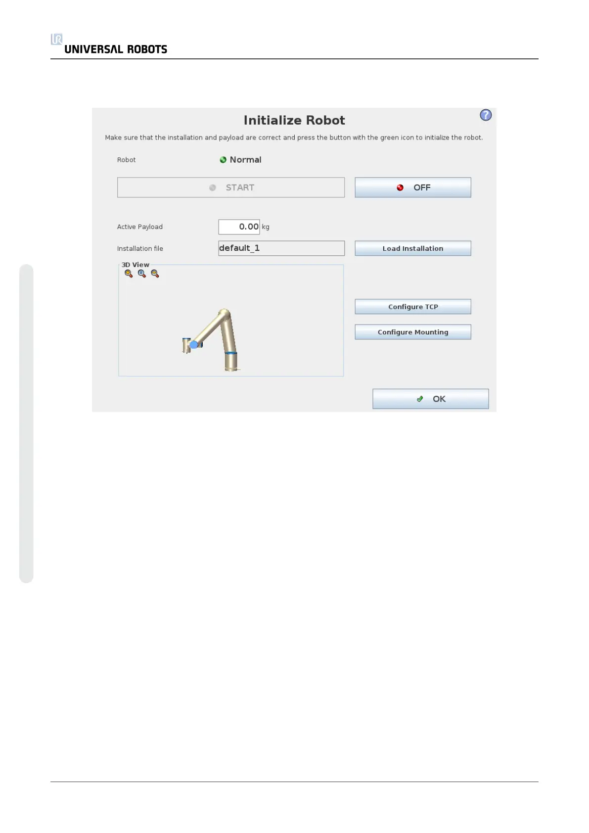
1.21.6. Initialization Screen
On this screen you control the initialization of the robot arm.
Robot arm state indicator
The status LED gives an indication of the robot arm’s running state:
• A bright red LED indicates that the robot arm is currently in a stopped state where the
reasons can be several.
• A bright yellow LED indicates that the robot arm is powered on, but is not ready for normal
operation.
• Finally, a green LED indicates that the robot arm is powered on, and ready for normal
operation.
The text appearing next to the LED further specifies the current state of the robot arm.
Active payload and installation
When the robot arm is powered on, the payload mass used by the controller when operating the
robot arm is shown in the small white text field. This value can be modified by tapping the text
field and entering a new value.
Note: setting this value does not modify the payload in the robot’s installation (see1.23.6.
Installation → TCP Configurationon page127), it only sets the payload mass to be used by the
controller.
UR10 114 User Manual
Copyright © 2009–2020 by UniversalRobotsA/S. All rights reserved.