1.30.1. MAF light guard interface
The 24V is shared with the 24V [ZA9-ZC9] in the EUROMAP 67 cable. However, the input
signals to the controller box are low current types and therefore most of the current is available.
It is recommended to keep the load under 1.2A. The 24V current and voltage is shown on the
EUROMAP 67 I/O tab.
The two MAF signals must connect to potential free switch contacts. The MAF signals are
0V/0mA when the ,,Moulding Area Free (Software)” bit is off.
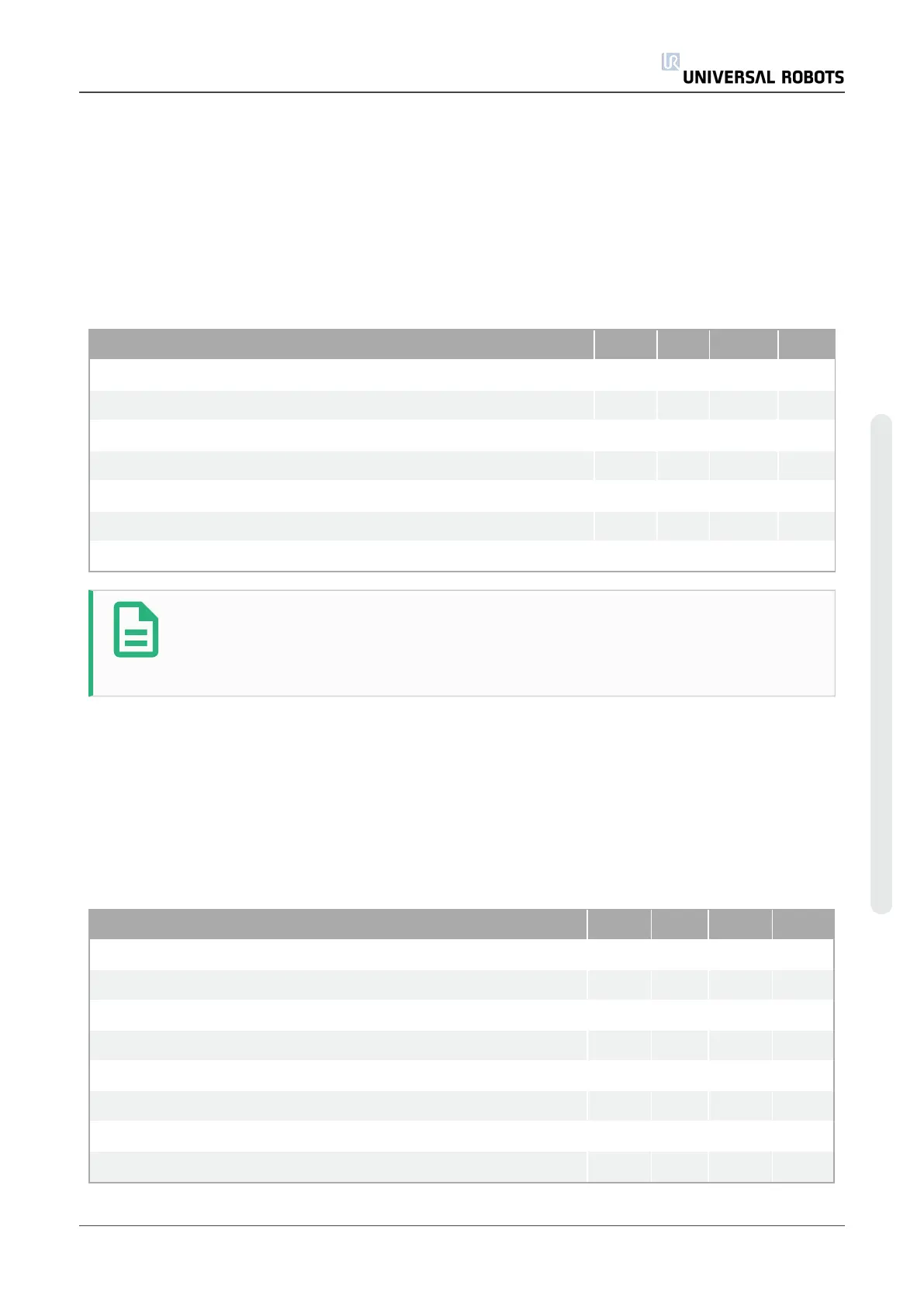
Parameter Min Typ Max Unit
24V Voltage tolerance -15% - +20% -
Current available from 24V supply - - 2.0* A
Overload protection - 2.2 - A
[MAF-MAF] Voltage when disconnected 0 12 12.5 V
[MAF-MAF] Current when connected 0 57 70 mA
[MAF-MAF] Protection against wrong connection - 400 - mA
[MAF-MAF] Protection against wrong connection -18 - 30 V
NOTE
The ,,MAF light guard interface” signals are not galvanically isolated from the
shield of the controller box.
1.30.2. Emergency stop, safety devices and MAF signals
The signals signalling emergency stop and MAF to the IMM are controlled by force guided safety
relays conforming to EN 50205. The switch contacts are galvanically isolated from all other
signals and conforms to IEC 60664-1 and EN 60664-1, pollution degree 2, overvoltage category III.
The signals signalling emergency stop and safeguard stop (safety devices) to the robot are
connected to the potential of the controller box.
Parameter Min Typ Max Unit
[C1-C2][C3-C4] Voltage 10.2 12 12.5 V
[C1-C2][C3-C4] Current (Each output) - - 120 mA
[C1-C2][C3-C4] Current protection - 400 - mA
[A1-A2][A3-A4] Input voltage -30 - 30 V
[A1-A2][A3-A4] Guaranteed OFF if -30 - 7 V
[A1-A2][A3-A4] Guaranteed ON if 10 - 30 V
[A1-A2][A3-A4] Guaranteed OFF if 0 - 3 mA
[A1-A2][A3-A4] ON Current (10-30V) 7 - 14 mA
User Manual 233 UR10
EUROMAP 67 Interface
Copyright © 2009–2020 by UniversalRobotsA/S. All rights reserved.