If the current position of the robot TCP comes close to a safety or trigger plane, or the orientation
of robot tool is near the tool orientation boundary limit (see 1.20.12. Boundarieson page97), a
3D representation of the boundary limit is shown.
When the robot is running a program, the visualization of boundary limits will be disabled.
Safety planes are visualized in yellow and black with a small arrow representing the plane
normal, which indicates the side of the plane on which the robot TCP is allowed to be positioned.
Trigger planes are displayed in blue and green and a small arrow pointing to the side of the plane,
where the Normal mode limits (see 1.20.6. Safety Modeson page91) are active.
The tool orientation boundary limit is visualized with a spherical cone together with a vector
indicating the current orientation of the robot tool. The inside of the cone represents the allowed
area for the tool orientation (vector).
When the target robot TCP no longer is in the proximity of the limit, the 3D representation
disappears. If the TCP is in violation or very close to violating a boundary limit, the visualization
of the limit turns red.
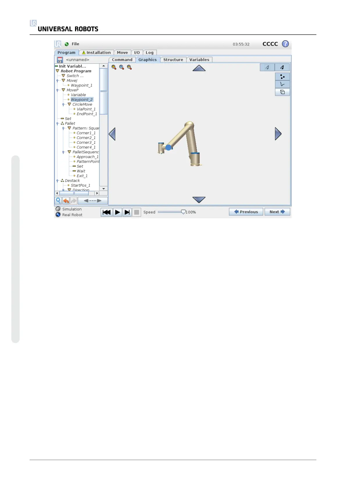
The 3D view can be zoomed and rotated to get a better view of the robot arm. The buttons in the
top-right side of the screen can disable the various graphical components in 3D view. The bottom
button switches on/off the visualization of proximate boundary limits. The motion segments
shown depend on the selected program node. If a Move node is selected, the displayed path is
the motion defined by that move. If a Waypoint node is selected, the display shows the following
∼ 10 steps of movement.
UR10 202 User Manual
Copyright © 2009–2020 by UniversalRobotsA/S. All rights reserved.