The safety settings consist of a number of limit values used to constrain the movements of the
robot arm, and of safety function settings for the configurable inputs and outputs. They are
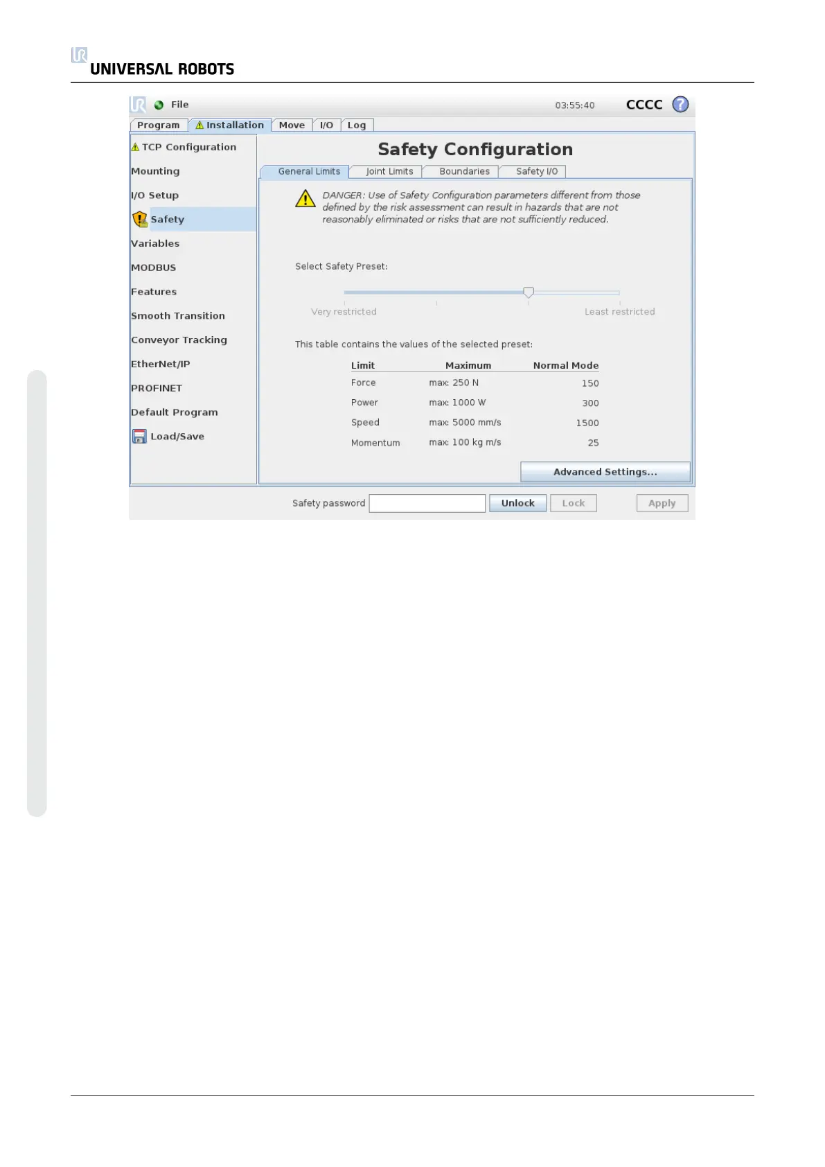
defined in the following subtabs of the safety screen:
• The General Limits subtab defines the maximum force, power, speed and momentum
of the robot arm. When the risk of hitting a human or colliding with a part of its
environment is particularly high, these settings need to be set to low values. If the risk is
low, higher general limits enable the robot to move faster and exert more force on its
environment. For further details, see1.20.10. General Limitson page93.
• The Joint Limits subtab consists of joint speed and joint position limits. The joint
speed limits define the maximum angular velocity of individual joints and serve to further
limit the speed of the robot arm. The joint position limits define the allowed position range
of individual joints (in joint space). For further details, see1.20.11. Joint Limitson page96.
• The Boundaries subtab defines safety planes (in Cartesian space) and a tool orientation
boundary for the robot TCP. The safety planes can be configured either as hard limits for
the position of the robot TCP, or triggers for activating the Reduced mode safety limits
(see1.20.12. Boundarieson page97.1.20.6. Safety Modeson page91). The tool orientation
boundary puts a hard limit on the orientation of the robot TCP. For further details, see
• The Safety I/O subtab defines safety functions for configurable inputs and outputs
(see1.23.2. I/O Tabon page123). For example, Emergency Stop can be configured as an
input. For further details, see1.20.13. Safety I/Oon page104.
UR10 88 User Manual
Copyright © 2009–2020 by UniversalRobotsA/S. All rights reserved.