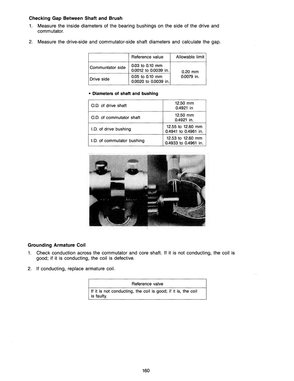
Checking Gap Between Shaft and Brush
1.
Measure the inside diameters of the bearing bushings
on
the side of the drive and
commutator.
2.
Measure the drive-side
and
commutator-side shaft diameters
and
calculate the
gap.
Reference value Allowable limit
Communtator side
0.03
to
0.10
mm
0.0012
to 0.0039 in.
0.20 mm
Drive side
0.05
to
0.10
mm
0.0079
in.
0.0020 to 0.0039 in.
• Diameters of shaft and bushing
D.D.
of drive shaft
12.50 mm
0.4921
in
D.D.
of commutator shaft
12.50 mm
0.4921
in.
I.D.
of drive bushing
12.55 to
12.60
mm
0.4941
to
0.4961
in.
I.D.
of commutator bushing
12.53 to 12.60 mm
0.4933 to
0.4961
in.
Grounding Armature Coil
1.
Check conduction across the commutator and core shaft. If it
is
not conducting, the coil
is
good; if it
is
conducting, the coil
is
defective.
2.
If conducting, replace armature coil.
Reference valve
If it is not conducting, the coil is good; if it
is,
the coil
is faulty.
160