INLET AND EXHAUST
VALVES
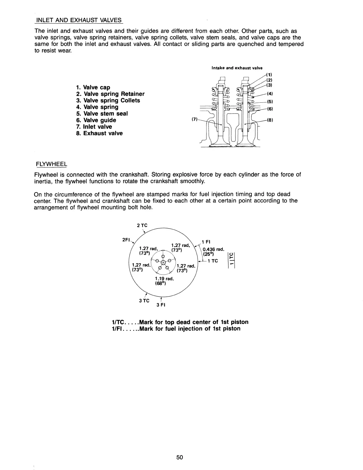
The inlet and exhaust valves and their guides are different from each other. Other parts, such
as
valve springs, valve spring retainers, valve spring collets, valve stem seals, and valve caps are the
same for both the inlet and exhaust valves. All contact or sliding parts are quenched and tempered
to resist
wear.
1.
Valve cap
2. Valve spring Retainer
3.
Valve spring Collets
4.
Valve spring
5.
Valve stem seal
6.
Valve guide
7.
Inlet valve
8.
Exhaust valve
FLYWHEEL
(7)
Intake and exhaust valve
(4)
~_-(5)
(6)
(8)
Flywheel is connected with the crankshaft. Storing explosive force by each cylinder
as
the force of
inertia, the flywheel functions to rotate the crankshaft smoothly.
On
the circumference of the flywheel are stamped marks for fuel injection timing and top dead
center. The flywheel and crankshaft can
be
fixed
to
each other at a certain point according to the
arrangement of flywheel mounting bolt hole.
2TC
2FI"
1
1.27 rad
•
(73°)
•
27
r~ad.
(730)
1.27 rad. 1.27 rad.
(73°)
(7JD)
1.19 rad.
(68°)
1 TC
\~
1/TC .
....
Mark
for
top
dead center
of
1st piston
1/FI
......
Mark for fuel injection
of
1st piston
50