Operation
Section
LX 31/41 Work Platform3-4
3.2
3.2 Controls and Indicators
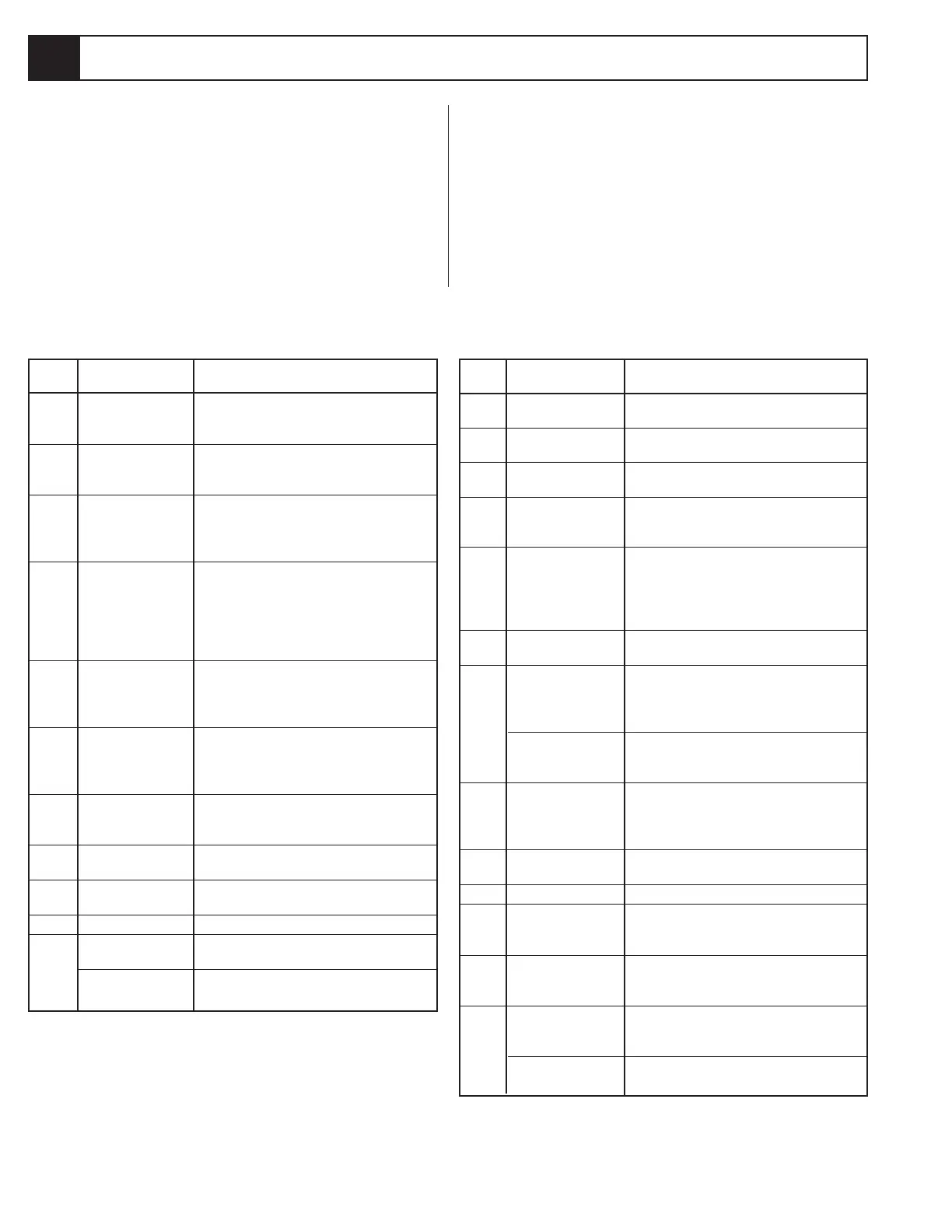
The controls and indicators for operation of the LX 31/41
Work Platform are shown in Figure 3-1. The name and
function of each control and indicator are listed in Table
3-1. The index numbers in Figure 3-1 correspond to the
index numbers in Table 3-1. The operator shall know
the location of each control and indicator and have a
thorough knowledge of the function and operation of
each before attempting to operate the unit.
3.1
Controller/Platform
INDEX
NO. NAME FUNCTION
12 HOURMETER Tracks the number of hours of engine
(optional) powered operation.
13 RAISE Press button to lift the platform and
BUTTON
14 LOWER Press button to lower the platform.
BUTTON
15 EMERGENCY STOP Push red button to cut power to all
SWITCH controls (off). Turn clockwise to provide
power (on).
16 FUEL SELECTOR Turning switch left or right changes the
SWITCH engine's fuel supply between GASOLINE
(Dual Fuel Only) and PROPANE. Placing the switch in the
center position purges the fuel lines prior
to changing fuels.
17 EMERGENCY Pull out to lower the platform in the
LOWERING VALVE event of powered function failure.
18 DOWN ALARM* Sounds an audible signal while
platform is lowering during normal
operation. If the Emergency Lowering
Valve is used the alarm does not sound.
TILT ALARM* Sounds an audible signal when the
platform is elevated and on a slope of 2°
side to side or fore and aft.
19 BRAKE RELEASE Releases the Parking Brake allowing the
PUMP machine to be moved in the event power
is lost or for winching onto a trailer. See
Section 3.5.
20 START BUTTON Press to start the engine. Release after
engine starts.
21 STOP BUTTON Press to kill the engine.
22 THROTTLE BUTTON Press to increase engine RPM when
operating functions from the lower
control panel.
23 PLATFORM / CHASSIS Turn switch to the left to enable platform
SWITCH controls. Turn switch to the right to enable
chassis controls.
24 CHOKE BUTTON Press to engage choke when starting
(gasoline / dual fuel) engine.
GLOW PLUG BUTTON
Press and hold for 6 seconds to preheat
(diesel) glow plugs before starting.
* Down Alarm and Tilt Alarm are the same unit with
different inputs.
Chassis
Table 3-1: Controls and Indicators
INDEX
NO. NAME FUNCTION
1 KEY SWITCH Turn key fully clockwise to start engine,
when released key goes to RUN to provide
power to the Interlock Switch.
2 EMERGENCY STOP Push red button to cut power to all
SWITCH controls (off). Turn clockwise to provide
power (on).
3 CONTROL LEVER Move joystick forward or backwards to
control Drive and Lift Valves proportionally
or Down Valve depending on position of
Drive Lift Switch.
4 STEERING SWITCH Moving the momentary rocker switch RIGHT
or LEFT steers the work platform in that
direction. Although the Steering Switch is
self centering the steering system is not.
The wheels must be steered back to
straight.
5 DRIVE SPEED/ Provides two speed/torque ranges, in
TORQUE SELECTOR forward or reverse.
SWITCH HIGH SPEED-low torque and
HIGH TORQUE-low speed.
6 DRIVE/LIFT Selecting DRIVE allows the work platform
SWITCH to move forward or reverse. Selecting
LIFT allows the work platform to raise or
lower.
7 INTERLOCK Provides power to the Controller powered
LEVER functions, only when depressed, preventing
SWITCH accidental activation of the Controller.
8 DRIVE ENABLE Illuminates when drive is enabled, turns
INDICATOR off when disabled.
9 OUTRIGGER Push up to extend outriggers, down to
SWITCHES retract them.
10 ORBIT LEVEL Use when leveling machine with outriggers.
11 CHOKE BUTTON Press to engage choke when starting
(gasoline / dual fuel) engine.
GLOW PLUG BUTTON
Press and hold for 6 seconds to preheat
(diesel) glow plugs before starting.
 Loading...


