Introduction & Specifications
Section
LX 31/41 Work Platform 1-1
1.0 Introduction
PURPOSE
The purpose of this service and parts manual is to
provide instructions and illustrations for the operation
and maintenance of the LX 31/41 Work Platform manu-
factured by UpRight, Inc. of Selma, California.
SCOPE
The manual includes procedures for proper operation,
maintenance, adjustment, and repair of this product as well as
recommended maintenance schedules and troubleshooting.
1.1 General Description
The LX 31/41 Work Platform consists of the platform,
controller, elevating assembly, power module, control
module, and chassis.
Platform
The platform has a reinforced steel floor, 43.5 inch (1.11 m)
high guardrails with midrail, 6 inch (152 mm) toeboards
and an entrance gate at the rear of the platform. The
guardrails can be folded down for access through doors
or for shipment.
DO NOT use the maintenance platform
without guardrails properly assembled and
in place.
Controller
The controller contains the controls to operate the
machine. It should be hung on the front, left, or right
guardrail, but may be hand held if necessary. To operate
the machine, the interlock lever must be depressed to
operate any function. A complete explanation of control
functions can be found in Section 3.
Elevating Assembly
The platform is raised and lowered by the elevating assem-
bly; a three (LX 31), or four (LX41) section scissor assembly
powered by a single stage lift cylinder. The hydraulic
pump, driven by the engine, powers the cylinder. Solenoid
operated valves control raising and lowering.
Power Module
The power module contains the engine, hydraulic pump,
hydraulic reservoir, and starter solenoid.
Control Module
The control module contains the L.P. bottle and/or fuel
tank, hydraulic valve manifold, horn/alarms, volt/hour
meter, electrical terminal strips, battery, and chassis control
panel. A complete explanation of the chassis control
functions is found in Section 3.
Chassis
The chassis is a structural frame that supports all the
components of the LX 31/41 Work Platform.
PURPOSE OF EQUIPMENT
The objective of the LX 31/41 Work Platform is to
provide a quickly deployable, self propelled, variable
height work platform to elevate personnel and materials
to overhead work areas and be driven over rough terrain
(4WD model only).
SPECIAL LIMITATIONS
Travel with the platform raised is limited to a creep
speed range.
Elevating of the Work Platform is limited to firm, level
surfaces only. Any degree of slope greater than 2
o
will
lockout the elevating circuits and sound a warning alarm.
Four wheel models: driving while elevated is limited to
flat surfaces only. Any degree of pitch in the front axle
will lockout the drive, and axle floating circuits when
elevated.
The elevating function shall ONLY be used
when the work platform is level and on a
firm surface. The work platform is NOT
intended to be driven over uneven, rough
or soft terrain when elevated.
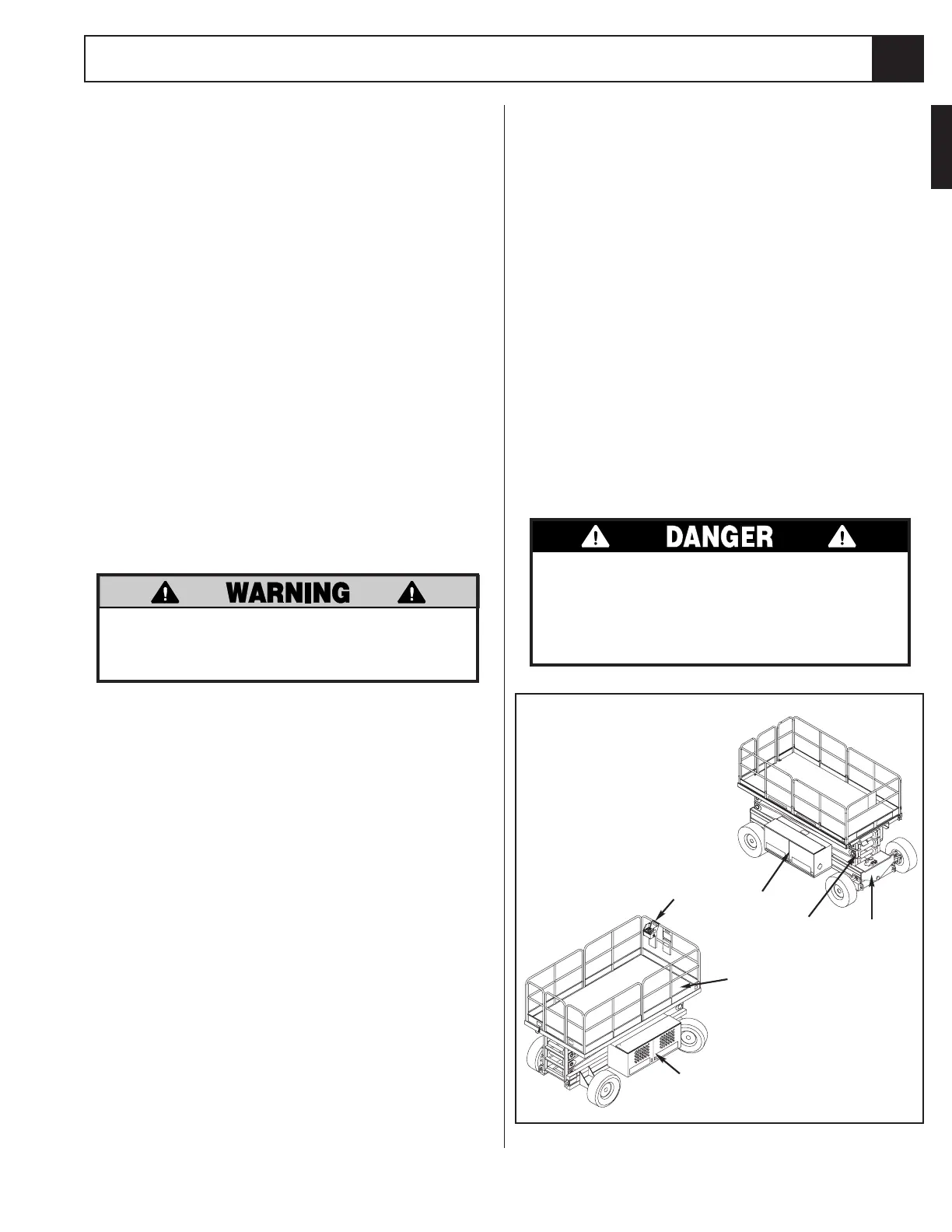
Figure 1-1: LX 31/41 Work Platform
1.0
2
1
4
3
6
5
4. Power Module
5. Control Module
6. Chassis
1. Platform
2. Controller Assembly
3. Elevating Assembly

 Loading...


