Section
4-9LX 31/41 Work Platform
Maintenance
4.6
Figure 4-11: Tilt Sensor
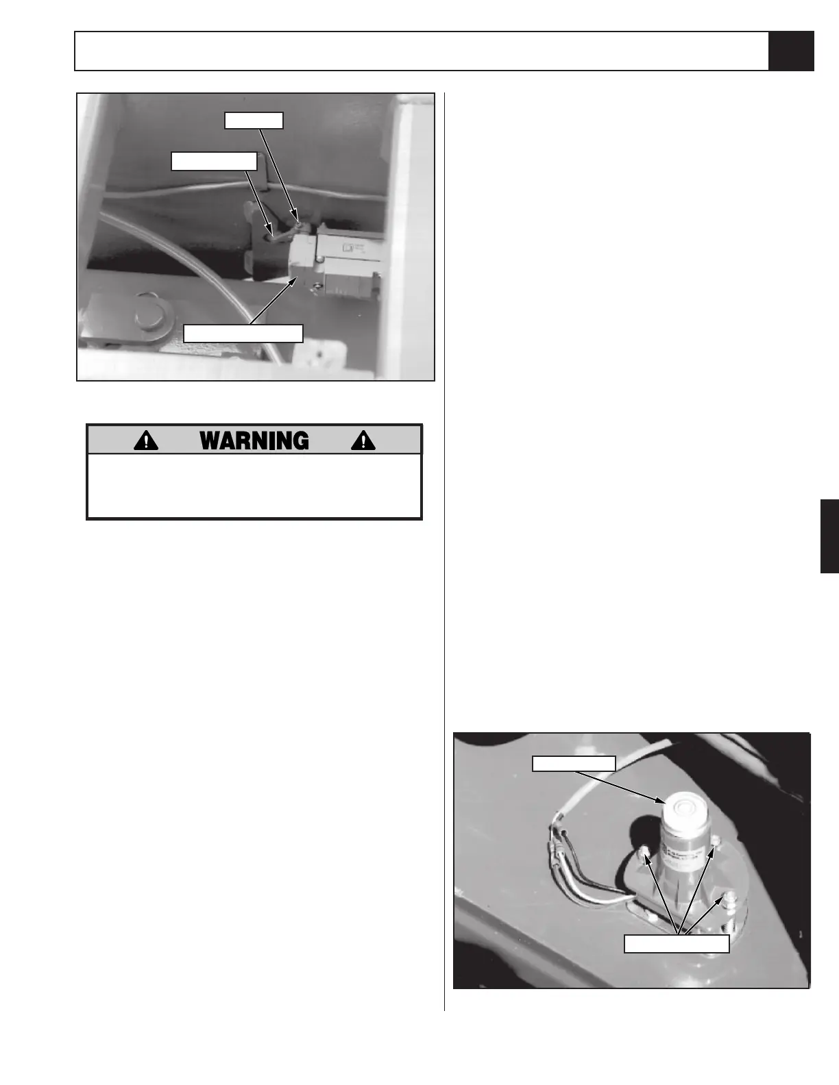
AXLE CENTER SWITCH (Figure 4-10)
1. Place the work platform on a level surface with the
front and rear axles parallel (on the same plane).
Verify this using an inclinometer.
2. Loosen the setscrew on the lever of the limit switch.
It should immediately spring to center. Tighten the
setscrew.
3. Test the switch function by moving the machine to a
location where the front axle will articulate off of
center and raising the platform until the magnetic
switches open (about 10 feet [3m]). The work
platform should not drive. Retest with the axle off
center in the other direction.
TILT SENSOR (Figure 4-11)
The Tilt Sensor has three wires; red-power (12V in),
black-ground, white-output (12v out). To verify the
sensor is working properly there are two LED's under the
sensor; green indicates the sensor is on (has power), red
indicates the sensor is level and the white wire is 'hot'
(12v out).
1. Check tires for proper pressure.
2. Place machine on firm level surface ± ¼°.
3. Use Inclinometer to ensure that the front and rear of
the Chassis are level within± ¼°.
4. Adjust the three leveling locknuts until the bubble is
centered in the circle on the attached bubble level.
5. Elevate the platform until the magnetic switches
open (about 10 feet [3m]) and push the tilt sensor
base to test the alarm circuit. Alarm should sound.
Setscrew
Axle Center Switch
Actuator Arm
Adjustment Nuts
Bubble Level
Figure 4-10: Axle Center Switch
DO NOT attempt to adjust Limit Switches
without first blocking the elevating assem-
bly (see section 4.3).
1. Lower the Platform completely.
2. With the Platform / Chassis switch on Chassis, push
the Tilt Sensor base to test the alarm circuit.
3. If the alarm sounds, elevate the Platform and adjust
the position of the switch mounting bracket by
loosening the capscrews and nuts holding the
bracket in place and moving the bracket until the
switches align with the magnets. Lower the Platform
and retest. When switches are aligned, alarm will
not sound while platform is lowered.
4. With platform elevated, repeat step 2. When
switches are properly adjusted, alarm will sound.
 Loading...


