Section
4-12 LX 31/41 Work Platform
Maintenance
4.8
4.9 Hydraulic Brakes, Drive
Motors, And Hubs
REAR AXLE (Figure 4-14)
Removal
1. Park the work platform on firm level ground and block
the wheels to prevent the work platform from rolling.
2. Loosen the wheel nuts on the torque hub to be removed.
3. Raise the rear of the work platform using a 2-ton jack.
4. Position 2 1-ton jack stands under the rear axle to
prevent the work platform from falling if the jack fails.
5. Remove the wheel lug bolts and wheel.
6. Tag and disconnect the hose assemblies from the
drive motor and brake.
Clean all fittings before disconnecting the
hose assemblies.
Plug all port holes and hose assemblies
IMMEDIATELY to prevent contamination
from dust and debris.
Note: when disassembling, retain gaskets between
components, they may be reused if undamaged.
7. Remove the four capscrews holding the motor to the
brake. Remove the motor.
8. Remove the two socket head through bolts connecting
the brake and the torque hub. Remove the brake.
9. Remove the eight capscrews connecting the torque
hub to the rear axle. Remove the torque hub.
4.8 Hydraulic Pump
(Figure 4-13)
NOTE: If the hydraulic tank has not been drained,
suitable means for plugging the hoses should be
provided to prevent excessive fluid loss.
REMOVAL
1. Mark, disconnect and plug the hose assemblies.
2. Loosen the capscrews and remove the pump assem-
bly from the engine.
INSTALLATION
1. Torque each capscrew a little at a time until both
capscrews are torqued to 20 ft. lbs. (27 N-m).
2. Unplug and reconnect the hydraulic hoses.
3. Fill the pump completely with clean hydraulic oil by
pouring it into the drain line cavity.
4. Check the oil level in the hydraulic tank before
operating the work platform.
5. Set standby and maximum pressures, and horse-
power limiter nodes as outlined under Pump Setup
in section 4.5 setting hydraulic pressures.
Figure 4-13: Hydraulic Pump
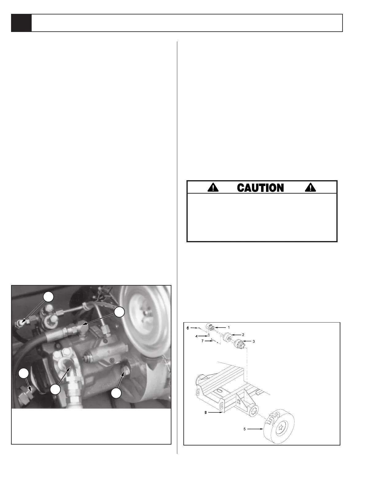
1. Drive Motor
2. Brake
3. Torque Hub
4. Bi-Directional Relief
5. Wheel
6. Capscrew
7. Capscrew
8. Chassis
Figure 4-14: Rear Axle Assembly
1
2
3
4
5
1. Sense Line
2. Inlet Line
3. Output Line
4. Drain Line
5. Capscew (typ.)

 Loading...


