Section
4-13LX 31/41 Work Platform
Maintenance
4.9
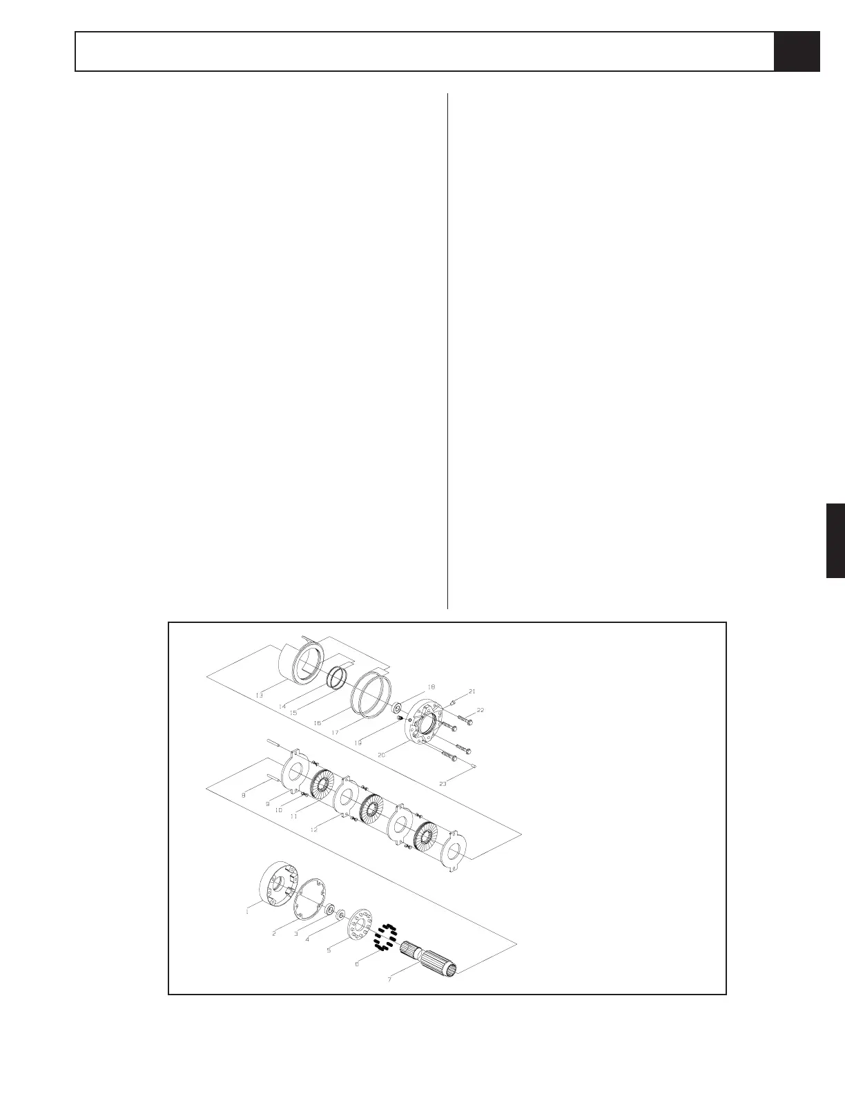
Figure 4-15: Brake Assembly
1. Housing
2. Gasket
3. Ball Bearing
4. Oil Seal
5. Spring Retainer
6. Spring, Compression
7. Shaft
8. Pin, Torque
9. Primary Disk
10. Spring, Compression
11. Rotating Disk.
12. Stationary Disk
13. Piston
14. Backup Ring
15. O-ring
16. Backup Ring
17. O-ring
18. Ball Bearing
19. Plug, Protective
20. Power Plate
21. Bleeder Screw
22. Capscrew
23. Pressure Relief Valve
Installation
1. Install the torque hub to the rear axle. Align the
holes and install the eight capscrews, tighten.
2. Coat the output shaft of the brake with high pressure
molybdenum grease and install brake into torque
hub. Align holes and install the two socket head
through bolts, tighten.
3. Coat the output shaft of the drive motor with high
pressure molybdenum grease and install into brake.
Align holes and install the four capscrews, tighten.
4. Reinstall the hose assemblies to the drive motor and
brake.
5. Reinstall the wheel and wheel nuts onto the torque
hub. Torque the wheel nuts to 90 ft. lbs. (122 N-m).
6. Remove the jack stands used to block the wheels.
Lower the jack and remove.
7. Operate the drive system to check for leaks. If the
brake was serviced, bleed out the air using the bleed
valve located on the brake housing.
Seal Replacement, Brake (Figure 4-15)
1. With shaft protrusion downward remove the cap-
screws (22) from the brake assembly.
2. Remove the power plate (20) from the housing (1).
3. Remove the gasket (2), discard.
4. Remove the piston (13) from the power plate (20)
by introducing low pressure air (15 psi) into the
hydraulic inlet. Make sure the piston is pointed
away from anyone.
5. Remove o-rings (15 & 17) and backup rings (14 & 16)
from the inner and outer diameter grooves of the
piston, discard.
6. Clean the piston (13) and power plate (20) assem-
blies with solvent. Inspect the sealing surfaces of the
piston (13) and power plate (20). Inspect the seal
grooves in the piston. Replace these parts if they are
damaged or scratched deeply. Lubricate piston
(13), power plate (20), and seals (14, 15, 16, & 17)
with clean hydraulic oil prior to assembly.
7. Install the backup rings (14 & 16) and o-rings (15 & 17)
into the seal grooves in the piston.
8. Install the piston into the power plate using a shop
press. Be careful not to damage the seals during
assembly. Center the cutouts in the piston with the
torque pin holes in the power plate. Press the
piston to a depth no less than flush, but not exceed-
ing 0.120 in. below the surface of the power plate at
the cutouts in the piston. This depth is critical, the
brake will not hold if it is exceeded.
9. Install gasket (2).
10. Install power plate / piston assembly (13 & 20) to
housing (1) using capscrews (22). Tighten sequen-
tially, one turn at a time, to press the two assemblies
together. Torque capscrews 50 to 60 ft.-lbs.
 Loading...


