Section
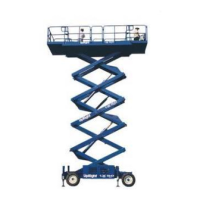
4-26 LX 31/41 Work Platform
Maintenance
4-13 Outrigger Cylinder
(Figure 4-25)
REMOVAL
1. Remove the plug from the top of the outrigger
cylinder.
2. Disconnect the wires from the pressure switch and
the ball switch. Tag them for identification during
reassembly.
3. Unscrew the strain relief and pull the wires out of
the top of the cylinder.
4. Remove and cap the hoses. Tag them for identifica-
tion during reassembly.
5. Remove the four capscrews, nuts, and washers
holding the outrigger cylinder to the outrigger
support weldment.
6. Remove the outrigger cylinder.
SEAL REPLACEMENT (FIGURE 4-26)
Note: Provide a clean work area for this operation,
and observe clean assembly practices. Seals and
hydraulic cylinder components are highly sensitive to
contamination that may not even be visible to the
naked eye.
1. Clamp barrel assembly into vise, using aluminum
sleeve to protect barrel from excessive scratches.
Remove counterbalance valve from barrel assembly ,
use extreme caution valve is under pressure.
2. Unthread mount plate bolt from barrel assembly
using a spanner wench, a sharp impact on wrench is
needed to loosen loctite from threads. Remove
mount plate from end of rod.
3. Unthread retaining nut and remove from barrel
assembly, using a spanner wrench.
4. Gently remove rod assembly from inside barrel
assembly using extreme caution not to damage
chrome plating on rod.
5. Remove seal retainer from rod assembly. Remove &
discard all seals from seal retainer (rod wiper, rod
seal, and static seal #1).
6. Clamp rod assembly in vise, using aluminum sleeve
to protect chrome plating from damage. Drill out
stakes on piston nut apply heat to threads on rod
and piston, to loosen loctite on threads. Remove
piston from rod assembly using spanner wrench.
7. Remove piston from rod, remove piston seal and
discard.
8. Clean all components with cleaning solvent. Clean
all loctite from foot pad bolt.
9. Apply a light coating of hydraulic oil to all seals and
sealing components prior to assembly.
Note: During seal replacement steps, do not use
sharp edged tools to avoid cutting the seals. After
assembling all seals, allow at least one hour for the
seals to elastically restore to their original shape
before assembly. Refer to Figure 4-26 for component
identification and placement.
10. Install rod wiper by folding into a 'C' shape and
allowing it to "snap" into the outer seal groove in the
seal retainer.
11. Install rod seal into inner seal groove in seal retainer
using above method.
12. Stretch static seal #1 into outer seal groove on seal
retainer.
13. Stretch piston seal into seal groove on piston.
14. Install seal retainer onto rod assembly, from piston
end of rod, using a sharp blow to seal retainer, with
hard rubber mallet, to overcome seal squeeze.
15. Apply Loctite
®
#262 (or equivalent) to rod end
threads. Install piston onto rod end, torque using
spanner wrench until tight.
16. Install rod assembly into barrel assembly, using extreme
caution not to damage chrome plating on rod.
17. Seat seal retainer into barrel using a sharp blow with
a hard rubber mallet to overcome seal squeeze.
18. Thread retaining nut onto barrel assembly, using
spanner wrench, tighten.
19. Apply Loctite
®
#242 (or equivalent) to threads of
foot pad bolt.
20. While holding foot pad in place at end of rod, install
foot pad bolt using spanner wrench, tighten.
INSTALLATION
1. Install the outrigger cylinder to the outrigger support
weldment using the four capscrews, nuts, and
washers; tighten.
2. Install the hoses exactly as disassembled.
3. Thread the wires for the pressure switch and the ball
switch through the strain relief.
4. Reattach the wires to the switches exactly as disas-
sembled.
5. Tighten strain relief.
6. Install plug to top of outrigger cylinder.
4.13

 Loading...