Section
4-6 LX 31/41 Work Platform
Maintenance
4.5
4.5 Setting Hydraulic Pressures
Note: Follow Pump Set - Up procedure whenever
Pump has been replaced, or when testing perfor-
mance to isolate possible failure. Refer to figure 4-6
for flow meter set - up.
PUMP SET-UP (Figure 4-5)
1. Remove Pump output line and cap it.
2. Install flow meter input line to Pump output.
3. Remove Tank return line and cap.
4. Install flow meter output line to Tank.
5. Remove sense line from Pump.
6. Install flow meter sense line to Pump.
7. Remove caps on Standby and Max Pressure adjust-
ment screws.
8. Press and hold Throttle Button to rev up engine.
9. Close simulated load flow control valve by turning
fully clockwise.
10. Turn Standby pressure adjustment screw fully clockwise.
11. Adjust Max Pressure to 3000 P.S.I. (clockwise to
increase, counterclockwise to decrease).
12. Turn Standby pressure adjustment screw counter-
clockwise until gauge reads 200 P.S.I.
13. Replace caps on Standby and Max Pressure adjust-
ment screws.
14. Open simulated load flow control valve by turning
fully counterclockwise.
15. Open simulated load pressure relief valve by turning
fully counterclockwise.
16. Loosen large locknut on Horsepower Limiter Valve
and turn adjustment screw counterclockwise two full
turns.
17. Increase simulated load pressure relief valve by
turning clockwise until gauge reads 1500 P.S.I.
18. Turn Horsepower Limiter adjustment screw clock-
wise until flow meter reads 12 G.P.M.
19. Tighten large locknut on Horsepower Limiter Valve.
20. Loosen small locknut on Horsepower Limiter Valve
and turn adjustment screw counterclockwise two full
turns.
21. Increase simulated load pressure relief valve by
turning clockwise until gauge reads 2500 P.S.I.
22. Turn Horsepower Limiter Valve adjustment screw
clockwise until flow meter reads 7 G.P.M.
23. Tighten small locknut on Horsepower Limiter Valve.
24. Replace hoses.
Figure 4-6: Flow Meter Set-Up
LIFT RELIEF VALVE
1. Operate the hydraulic system 10 - 15 minutes to
warm the oil.
2. Remove the cap or loosen the locknut on the Lift
Relief Valve.
3. Turn the Lift Relief Valve adjustment screw counter-
clockwise two full turns.
4. Place rated load on the platform (2000 lbs for LX31,
1500 lbs for LX41)
5. Depress the Throttle Button, and the Raise Button to
lift the platform.
6. Slowly turn the Lift Relief Valve adjustment screw
clockwise until the platform begins to rise.
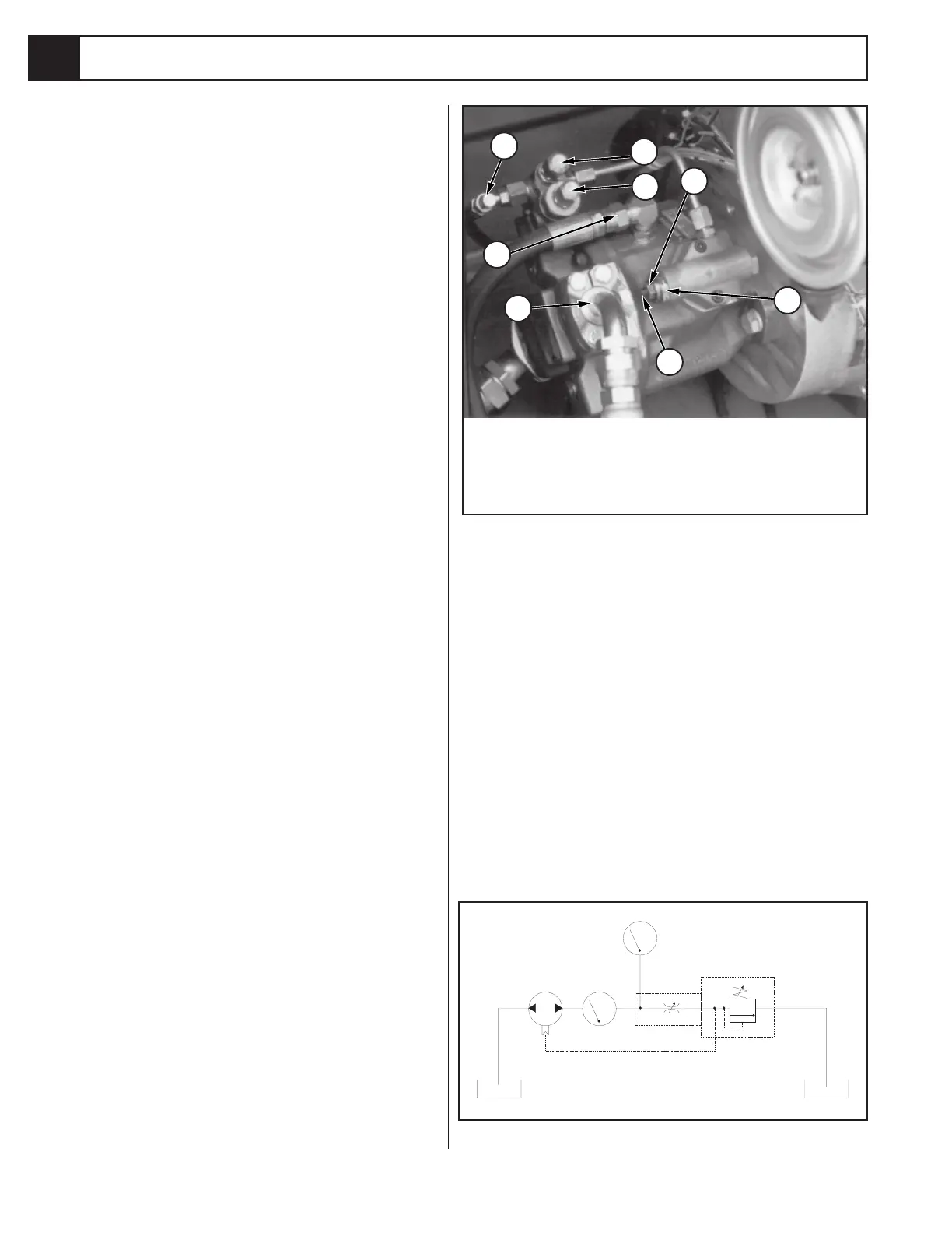
Figure 4-5: Hydraulic Pump
1
3
2
4
5
6
7
8
1. Sense Line
2. Standby PSI Adjustment
3. Max PSI Adjustment
4. Drain Line
5. Output Line
6. Horsepower Limiter
Adjustment Screw
7. Low PSI Locknut
8. High PSI Locknut
PRESSURE GUAGE
PUMP
SENSE LINE
FLOW METER
RELIEF VALVE
TANK
TANK
FLOW CONTROL
VALVE
SIMULATED LOAD
SIMULATED LOAD

 Loading...


