Section
4-7LX 31/41 Work Platform
Maintenance
4.5
9. Remove the gauge and replace the cap. Replace
the Green/White wire to terminal 17. Lower the
machine off of the jackstands.
STEERING RELIEF VALVES
1. Operate the hydraulic system 10 to 15 minutes to
warm the oil.
2. Install a 0-3000 P.S.I. gauge at the Main Pressure
Test Port.
3. Loosen the locknut or remove the cap on the Left
Steer Relief Valve.
4. Turn the adjustment screw two full turns counter-
clockwise.
5. Press the Steering Switch to the left and hold until
the system bypasses.
6. Turn the Steering Relief Valve adjustment screw
clockwise until the gauge reads 1500 P.S.I.
7. Tighten locknut or replace cap on Left Steering
Relief Valve.
8. Repeat process for Right Steering Relief Valve
BIDIRECTIONAL RELIEF VALVES
Note: Check or reset Drive Motor Relief Valves only
if you suspect that one of the Rear Wheels is not
turning due to premature bypass. This condition is
rare and Bidirectional Relief Valves should not be
reset as part of normal maintenance.
1. Operate the hydraulic system 10-15 minutes to
warm the oil.
2. Remove the cap and install a 0-3000 P.S.I. pressure
gauge at the Main Pressure Test Port.
3. Remove the Bidirectional Relief Valve from under
the rear drive motor and exchange with the Lift
Relief Valve.
4. Remove the cap from the Bidirectional Relief Valve
and turn the adjustment screw two full turns coun-
terclockwise.
5. Depress the Throttle Button and the Raise Button to
lift the platform to full height and hold until system
bypasses.
6. Turn the adjustment screw clockwise until the
pressure reaches 3000 P.S.I.
7. Replace the cap and return the Bidirectional Relief
Valve and the Lift Relief Valve to their original
positions.
8. Repeat as necessary for the other Bidirectional Relief
Valve.
9. Remove the gauge and replace the Test Port Cap.
7. Replace the cap, or tighten the locknut on the Lift
Relief Valve, and remove the load from the plat-
form.
COUNTERBALANCE VALVES
1. Operate the hydraulic system 10 to 15 minutes to
warm the oil.
2. Elevate the Front (4WD only), and Rear Wheels to
allow them to spin freely, and place on jackstands
suitable to support the weight of the machine.
3. Remove the Green/White wire from terminal 17 in
the Control Panel Assembly.
4. Install a 0-1000 P.S.I. pressure gauge at the Forward
Drive Pressure Test Port.
5. Loosen the locknut on the Reverse Counterbalance
Valve, push the control handle FORWARD, and
adjust the valve until the gauge reads 800 P.S.I.
(CW to decrease P.S.I., CCW to increase P.S.I.)
Tighten the locknut.
6. Install a 0-1000 P.S.I. pressure gauge at the Reverse
Drive Pressure Test Port.
7. Loosen the locknut on the Forward Counterbalance
Valve, push the control handle REVERSE, and adjust
the valve until the gauge reads 800 P.S.I. (CW to
decrease P.S.I., CCW to increase P.S.I.) Tighten the
locknut.
8. Recheck the pressures and adjust as necessary.
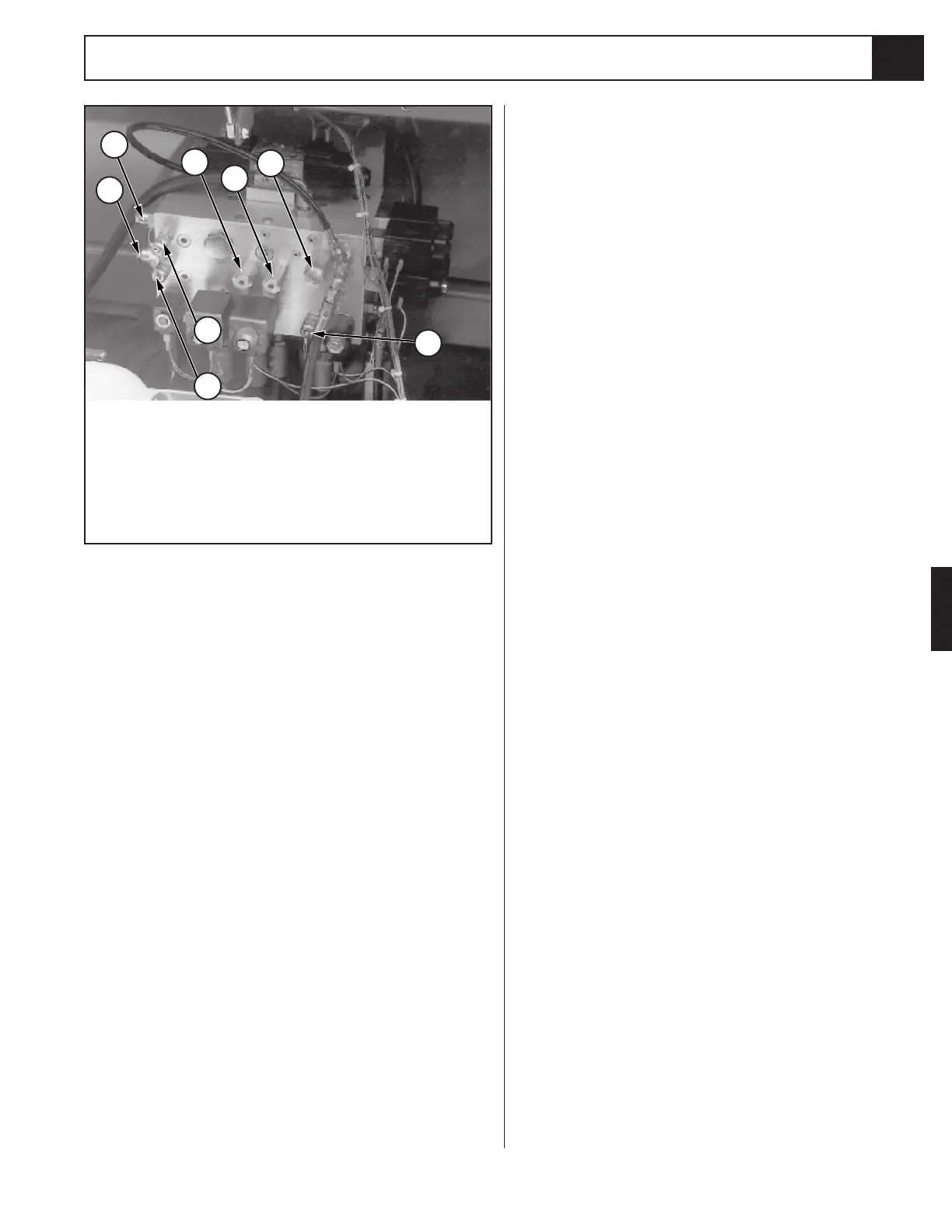
Figure 4-7: Valve Manifold
1
2
3
4
5
6
7
8
1. FWD Counter Balance Valve
2. REV Counter Balance Valve
3. FWD Drive PSI Test Port
4. REV Drive PSI Test Port
5. Steer Right Relief Valve
6. Steer Left Relief Valve
7. Lift Relief Valve
8. Main PSI Test Port

 Loading...


