Section
4-27LX 31/41 Work Platform
Maintenance
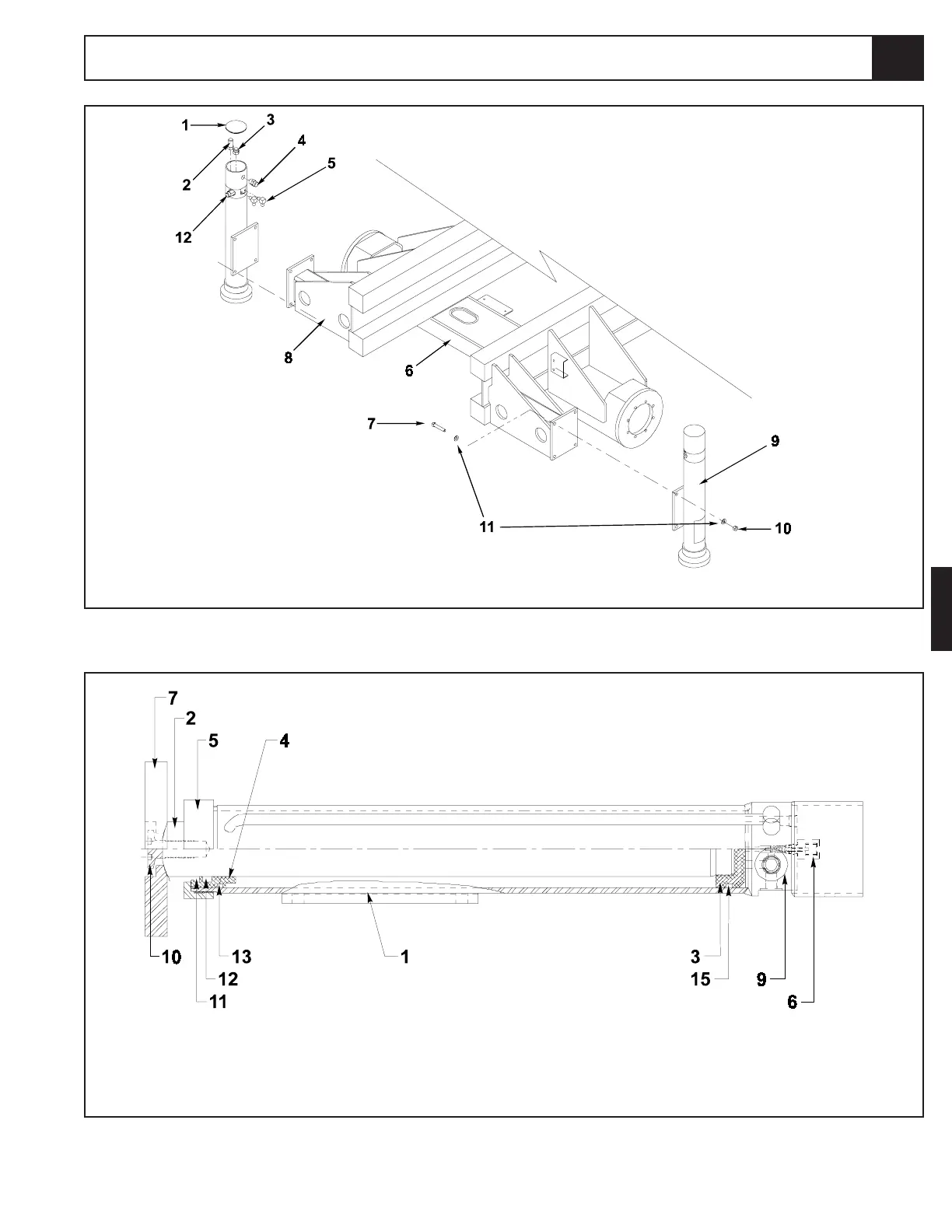
Figure 4-26: Outrigger Cylinder Cross Section
1. Plug
2. Pressure Switch (Outrigger Down Sensor)
3. Ball Switch (Outrigger Up Sensor)
4. Strain Relief
5. Fitting 90
o
6. Chassis Weldment
7. Capscrew
8. Outrigger Support Weldment
9. Outrigger Cylinder
10. Hex Nut
11. Washer
12. Counterbalance Valve
Figure 4-25: Outrigger Cylinder Installation
1. Barrel Assembly
2. Rod
3. Piston
4. Seal Retainer
5. Head Cap
6. Sensor Assembly
7. Foot Pad
9. Counterbalance Valve
10. Foot Pad Bolt
11. Rod Wiper
12. Rod Seal
13. Static Seal #1
15. Piston Seal
4.13

 Loading...


