Schematics
Section
LX 31/41 Work Platform 6-9
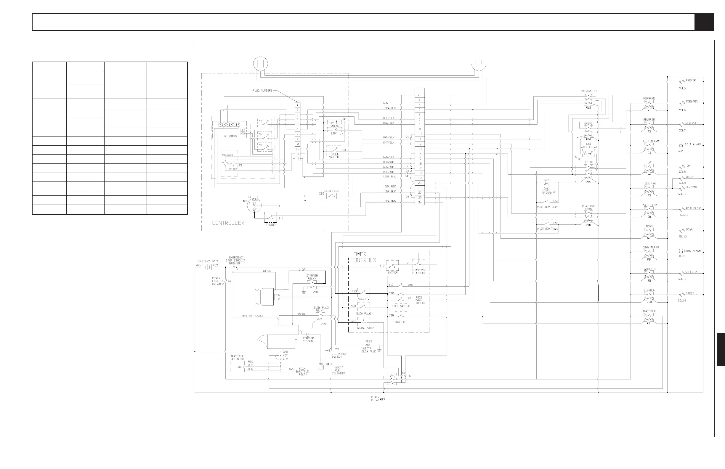
Figure 6-3: Electrical Schematic, Four Wheel Drive, Diesel Model (Serial Number 1000-1330)
6.1
REFERENCE
DESIGNATION NAME FUNCTION LOCATION
S19 Throttle Switch Supplies power to throttle Lower control box, in
relay. panel, top, first from
right.
S20 Glow Plug Switch Supplies power to glow Lower control box, in
plug relay. panel, second from top,
first from right.
SEN1 Level Sensor Provides power to cutout Control module.
relay when machine is level.
SOL1 Throtttle Solenoid Controls engine throttle. Power module, engine,
right side.
SOL2 Run Solenoid Controls fuel valve. Power module, engine,
on injection pump.
SOL5 Proportional Solenoid Controls proportional Right side of manifold,
valve. port marked 'G'.
SOL6 Forward Solenoid Controls forward valve. Right side of valve
manifold, port marked 'K'.
SOL7 Reverse Solenoid Controls reverse valve. Right side of manifold,
port marked 'L'.
SOL8 Lift Solenoid. Controls lift valve. Right side of manifold,
port marked 'J'.
SOL9 Shunt Solenoid Controls shunt valve. Front of manifold, port
markeed 'E'.
SOL10 Series / Parallel Solenoid Controls series / parallel Front side of manifold,
(two) valves. ports marked 'Q' & 'R'.
SOL11 Axle Float Solenoid Controls axle float valve. Front of manifold, port
marked 'F'.
SOL12 Down Solenoid Controls down valve. Lift cylinder, lower end.
SOL13 Steer Right Solenoid Controls steer valve when Top of manifold, on
steering right. steer valve.
SOL14 Steer Left Solenoid Controls steer valve when Top of manifold, on
steering left. steer valve.
Table 6-4: (cont.)
Note: See figure 6-17 for relay, terminal strip locations.

 Loading...


