Section
6-30 LX 31/41 Work Platform
Schematics
6.2
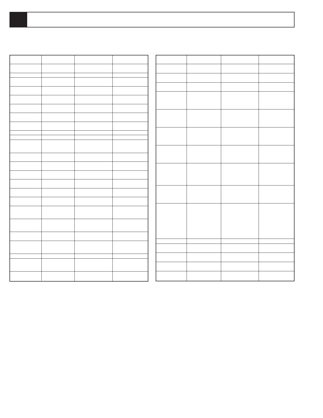
Table 6-15: Hydraulic Schematic Legend, Two Wheel Drive Model, With Outrigger Option
6.2 Hydraulic Schematics
REFERENCE
DESIGNATION NAME FUNCTION LOCATION
V1 Steering Valve Controls oil flow to Top of manifold, ports
steering cylinder (CYL1). marked 'D'.
V3 Proportional Valve Regulates oil flow to entire Right side of manifold,
lift and drive functions. port marked 'G'.
V4 Lift Valve Allows oil flow to lift Right side of manifold,
cylinder (CYL3). port marked 'J'.
V5 Forward Valve Allows oil flow to drive Right side of manifold
system in forward, allows port marked 'K'.
return oil flow from drive
system in reverse.
V6 Reverse Valve Allows oil flow to drive Right side of manifold
system in reverse, allows port marked 'L.
return oil flow from drive
system in forward.
V7 Forward Counter- Provides dynamic braking Left side ofmanifold,
balance Valve for machine in reverse port marked 'N'.
and prevents runaway on
slopes.
V8 Reverse Counter- Provides dynamic braking Left side ofmanifold,
balance Valve for machine in forward port marked 'O'.
and prevents runaway on
slopes.
V9,10 Series / Parallel Valves Directs oil flow to drive Front of manifold,
motors in either series ports marked 'R' & 'Q'.
(for higher speed) or
parallel (for higher torque)
configuration.
V11 Devider / Combiner Equalizes oil flow from Front of manifold, port
Valve front and rear drive marked 'P'.
motors when in parallel
(High Torque) configuration.
V12 Down Valve Holds oil in lift cylinder Base of lift cylinder,
(CYL3) when deck is (CYL3).
elevated. Allows oil to
flow out of cylinder when
deck is lowering. This
valve has a cable actuated
manual override for
emergency lowering.
V13-20 Counterbalance Valve Lock outrigger cylinders. On outrigger cylinders.
V21 Left Hand Front Controls oil flow to LHF Outrigger valve manifold,
Outrigger Valve outrigger cylinder. first valve from right.
V22 Right Hand Front Controls oil flow to RHF Outrigger valve manifold,
Outrigger Valve outrigger cylinder. second valve from right.
V23 Left Hand Rear Controls oil flow to LHR Outrigger valve manifold,
Outrigger Valve outrigger cylinder. third valve from right.
V24 Right Hand Rear Controls oil flow to RHR Outrigger valve manifold,
Outrigger Valve outrigger cylinder. fourth valve from right.
REFERENCE
DESIGNATION NAME FUNCTION LOCATION
CV1 Drive Make-up Check Prevents cavitation of down Inline valve located
stream motor when turning bottom of manifold.
CV2 Sense Line Check Not Used Not servicable
CV3-10 Outrigger Sense Line Allows oil flow to load Outrigger valve manifold.
Check Valves sense line only.
CYL1 Steering Cylinder Actuates steering linkage Front axle assembly
to steer front wheels.
CYL2 Axle Float Cylinder Locks front axle when Front axle assembly
platform is elevated.
CYL3 Lift Cylinder Actuates scissor linkage Scissor assembly
to elevate platform.
CYL4,5 Brakes, Multi-disc Parking brakes, spring Rear axle assembly
applied, hyd. release.
CYL6-9 Outrigger Cylinders Extend and retract to level Chassis assembly,
chassis. aft of each wheel.
MOT 1,2 Front Drive Motors Drive the front wheels. Front axle assembly
MOT 3,4 Rear Drive Motors Drive the rear wheels. Rear axle assembly
ORF1 Steering Orifice Limits the oil flow to the Under stack valve SV2
steering cylinder. between steer valve
(V1) and manifold.
ORF2 Down Orifice Limits the descent speed Under down valve
of the platform. (V12).
ORF3 Brake Orifice Allows brakes to release Left side top of manifold
quickly and apply slowly. under fitting in port 12.
ORF4 Outrigger Orifice Regulates speed of Under pump "P" fitting on
outrigger operation. outrigger valve manifold.
P1 Hydraulic Pump Provides fluid power for Power module, engine
hydraulic system. assembly.
P2 Brake Release Pump Used to release brakes Near rear axle assembly
when machine is towed. outside housing.
PS2-5 Outrigger Pressure Closes when outriggers Outrigger cylinders.
Switch are loaded.
RV1 Right Steer Relief Valve Provides overpressure Front of manifold, port
protection for steering marked 'A'.
components.
RV2 Right Steer Relief Valve Provides overpressure Front of manifold, port
protection for steering marked 'B'.
components.
RV3 Lift Relief Valve Limits maximum load Front of manifold port
of elevating assembly. marked 'I'.
RV4,5 Bi-Directional Relief Allows oil flow to bypass Underneath each rear
Valves drive motors when drive motor.
turning on tight radius.
SV1 Sense Line Shuttle Valve Not used. Not serviceable.
SV2 Sense Line Shuttle Valve Allows pilot pressure to Stack valve located
pump sense line from between steering valve
steering. (V1) and manifold.
SV3 Drive Shuttle Valve Allows oil pressure from Not serviceable.
drive to release brakes.
Note: See figure 6-18 , 19 for hydraulic valve locations.

 Loading...


