42 • vacon description of parameters
Tel. +358 (0)201 2121 • Fax +358 (0)201 212 205
7
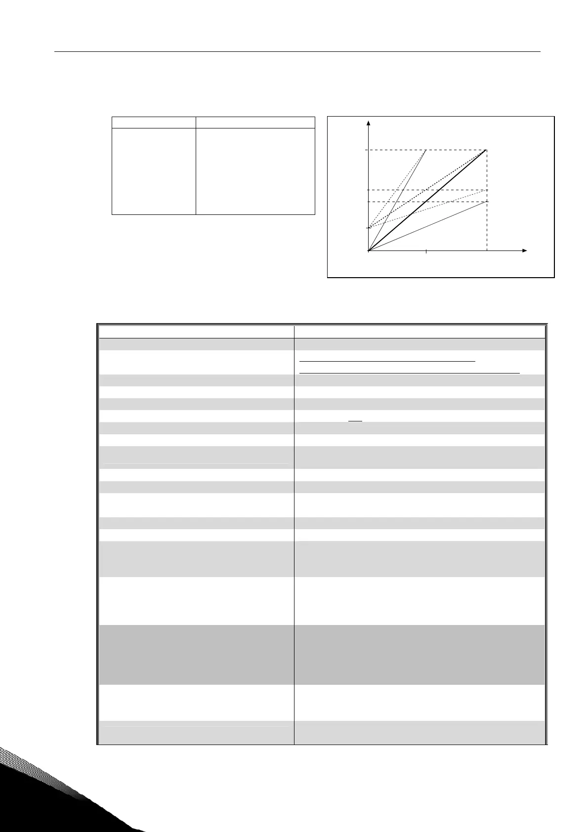
311 Analogue output scale
(2.3.5.6)
Scaling factor for analogue output.
Signal Max. value of the signal
Output frequency Max frequency (par.ID102)
Freq. Reference Max frequency (par.ID102)
Motor speed Motor nom. speed 1xn
mMotor
Output current Motor nom. current 1xI
nMotor
Motor torque Motor nom. torque 1xT
nMotor
Motor power Motor nom. power 1xP
nMotor
Motor voltage 100% x U
nmotor
DC-link voltage 1000 V
Table 31. Analogue output scaling
Figure 10. Analogue output scaling
312 Digital output function
(2.3.1.2)
Setting value Signal content
0 = Not used Out of operation
Digital output DO1 sinks the current and
programmable relay (RO1, RO2) is activated when:
1 = Ready The frequency converter is ready to operate
2 = Run The frequency converter operates (motor is running)
3 = Fault A fault trip has occurred
4 = Fault inverted A fault trip not occurred
5 = Vacon overheat warning
The heat-sink temperature exceeds +70°C
6 = External fault or warning Fault or warning depending on par. ID701
7 = Reference fault or warning
Fault or warning depending on par. ID700
- if analogue reference is 4—20 mA and signal is <4mA
8 = Warning Always if a warning exists
9 = Reversed The reverse command has been selected
10 = Preset speed 1 (Applications 2)
10 = Jogging speed (Applications 3456)
The preset speed has been selected with digital input
The jogging speed has been selected with digital input
11 = At speed The output frequency has reached the set reference
12 = Motor regulator activated Overvoltage or overcurrent regulator was activated
13 = Output frequency limit supervision
The output frequency goes outside the set supervision
low limit/high limit (see parameter ID's 315 and 316
below)
14 = Control from I/O terminals (Appl. 2)
14 = Output freq.limit 2 supervision
(Applications 3456)
I/O control mode selected (in menu M3)
The output frequency goes outside the set supervision
low limit/high limit (see parameter ID's 346
and 347
below)
15 = Thermistor fault or warning (Appl.2)
15 = Torque limit supervision (Appl.3456)
The thermistor input of option board indicates
overtemperature. Fault or warning depending on par
ID732.
The motor torque goes beyond the set supervision low
limit/high limit (par. ID348 and ID349).
16 = Fieldbus input data (Application 2)
16 = Reference limit supervision
Fieldbus input data (FBFixedControlWord) to DO/RO.
Active reference goes beyond the set supervision low
limit/high limit (par. ID350 and ID351)
17 = External brake control (Appl. 3456)
External brake ON/OFF control with programmable
delay (par. ID352 and ID353)
1.0
0
20 mA
4 mA
10 mA
0.5
0 mA
NX12K18
12 mA
ID310 = 1
ID311 =
200%
ID311 =
100%
ID311 =
50%
ID310 = 0
Analogue
output
current
Max. value of signal
selected by ID307