description of parameters vacon • 43
24-hour support +358 (0)40 837 1150 • Email: vacon@vacon.com
7
18 = Control from I/O terminals (Appl.
3456)
External control mode (Menu M3; ID125)
19 = Frequency converter temperature
limit supervision (Appl. 3456)
Frequency converter heatsink temperature goes
beyond the set supervision limits (par. ID354 and
ID355).
20 = Unrequested rot. direction (Appl. 345)
20 = Reference inverted (Appl. 6)
Rotation direction is different from the requested one.
21 = External brake control inverted (Appl.
3456)
External brake ON/OFF control (par. ID352 and ID353);
Output active when brake control is OFF
22 = Thermistor fault or warning
(Appl.3456)
The thermistor input of option board indicates
overtemperature. Fault or warning depending on
parameter ID732.
23 = Fieldbus input data (Application 5)
23 = On/Off control (Application 6)
Fieldbus input data (FBFixedControlWord) to DO/RO.
Selects the analogue input to be monitored. See par.
ID356, ID357, ID358 and ID463.
24 = Fieldbus input data 1 (Application 6) Fieldbus data (FBFixedControlWord) to DO/RO
25 = Fieldbus input data 2 (Application 6) Fieldbus data (FBFixedControlWord) to DO/RO
26 = Fieldbus input data 3 (Application 6) Fieldbus data (FBFixedControlWord) to DO/RO
Table 32. Output signals via DO1
315 Output frequency limit supervision function
(2.3.4.1)
0 No supervision
1 Low limit supervision
2 High limit supervision
3 Brake-on control (See chapter Error! Reference source not found. on page Error!
Bookmark not defined.)
If the output frequency goes under/over the set limit (ID316) this function generates a
warning message via the digital output DO1 or via the relay output RO1
or RO2 depending on the settings of parameters ID312…ID314.
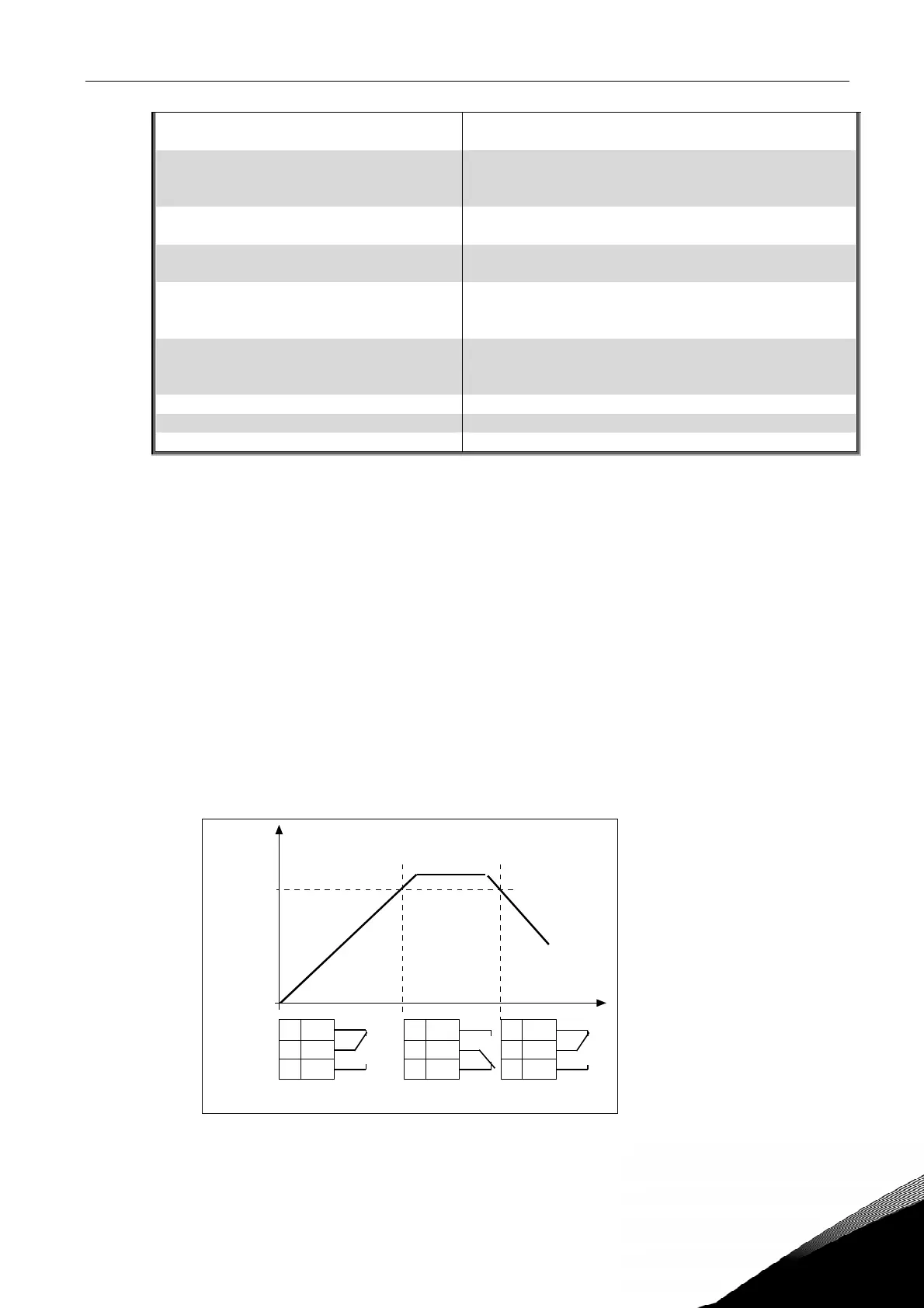
316 Output frequency limit supervision value
(2.3.4.2)
Selects the frequency value supervised by parameter ID315. See Figure 11.
Figure 11. Output frequency supervision
f[Hz]
t
21 RO1
22 RO1
23 RO1
21 RO1
22 RO1
23 RO1
21 RO1
22 RO1
23 RO1
NX12K19
Example:
ID316
ID315 = 2