8.2 Controller Hardware SPC5350 and 6350
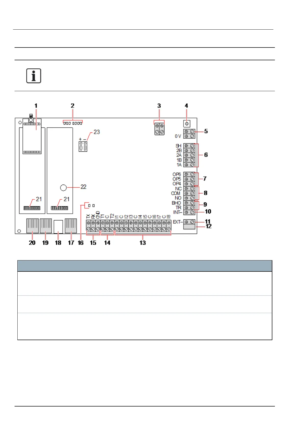
This section describes the SPC5350 and SPC6350.
The expander that is connected to the power supply within the G5 is set to ID1 by default. This setting
should not be changed.
Number Name Description
1 Optional
wireless
module
The controller PCB can be factory fitted with a wireless module for use with wireless
(868MHz) sensors.
2 SPC status
LEDs
These 7 LEDs display the status of various system parameters as described in
Controller status LEDs on page362.
3 Clock
Reference
A clock reference signal can also be applied to this 2-pin connector to maintain accurate
system time.
Connect to Clock Reference CN17 on SPCP355.300 Smart PSU.
SPC4xxx/5xxx/6xxx – Installation & Configuration Manual Controller hardware
© Vanderbilt 2018 71 A6V10276959-d
11.2018