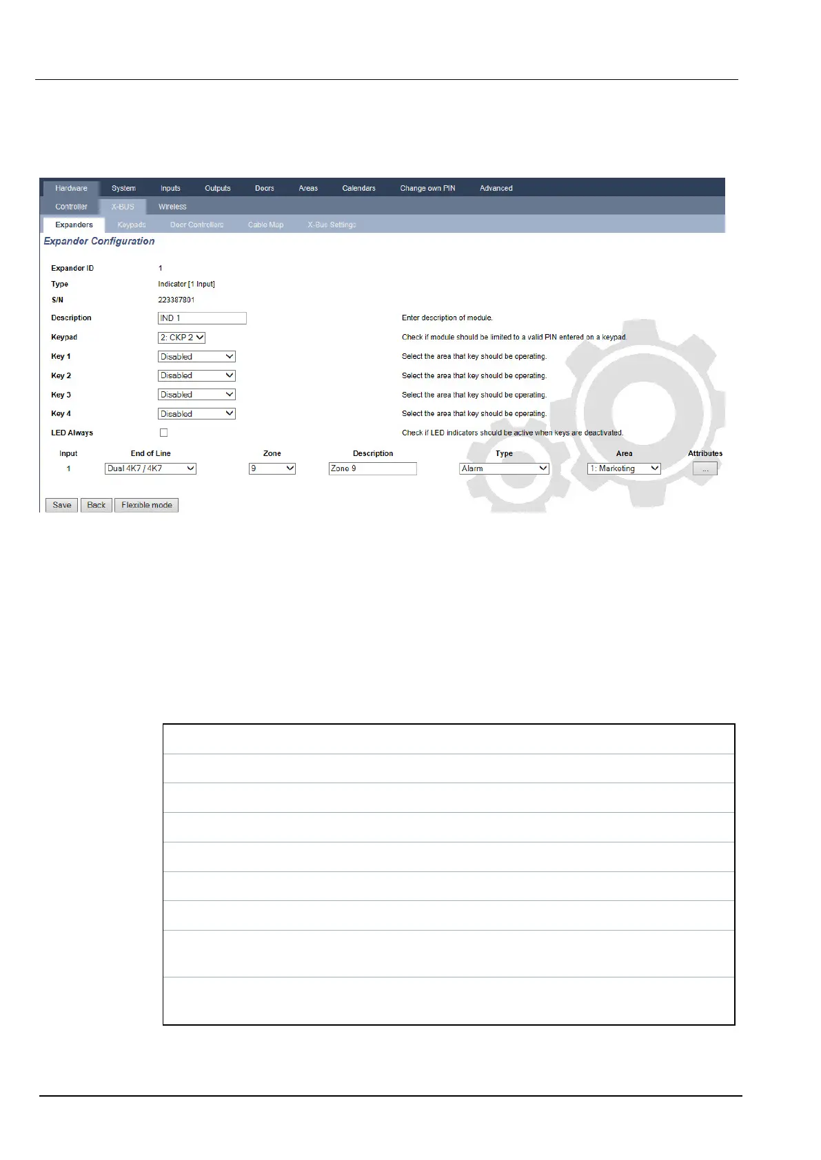
1. Select Configuration > Hardware > X-Bus > Expanders.
2. Click one of the indicator identifying parameters.
The following page is displayed for Linked Mode configuration.
Linked Mode
1. Enter a description.
2. Select if indicator module should be limited to a valid code entered on a keypad.
3. Select the areas that are to be controlled by the 4 functions keys.
4. Configure the input.
Flexible Mode
1. Click the Flexible Mode button.
2. Configure the fields described in the table below.
Function Keys
Area Select the area is to be controlled by the function key.
Function Select the function to be performed by this key in this area.
Area Select an area if the indicator module is located in a secure area.
Visual Indication
Indicator There are 8 indicators/LEDs on the right and 8 indicators/LEDs on the left side.
Function The function that is indicated by this LED.
Function
On
Select the colour and the state for every indicator if the selected function is ON.
Function
Off
Select the colour and the state for every indicator if the selected function is OFF.
SPC4xxx/5xxx/6xxx – Installation & Configuration Manual Engineer programming via the browser
© Vanderbilt 2018 241 A6V10276959-d
11.2018