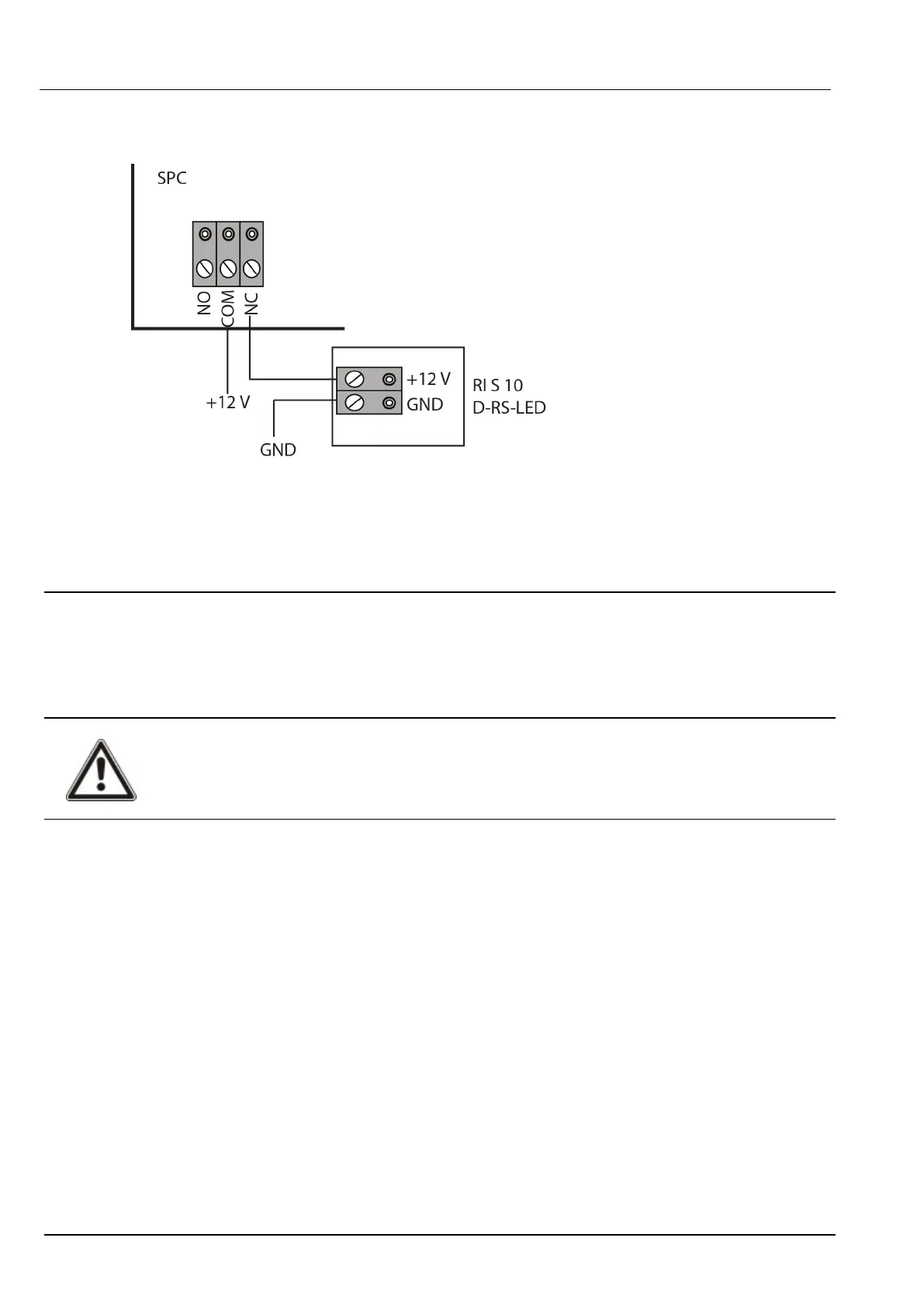
The following diagram shows how the glassbreak interface is wired to the SPC controller for power, or to
an 8-in/2-out expander:
For information on wiring the glassbreak interface to a zone, see the product-specific documentation.
For information on wiring the glassbreak sensors to the glassbreak interface, see the product-specific
documentation.
10.9 Installing plug-in modules
2 modems (PSTN or GSM) may be installed on the controller board to increase functionality. The picture
below shows the 2 slots available for each modem, the primary (left) slot and the back-up (right) slot.
If both modem slots are available, always install the plug-in module in the primary slot; the system always
attempts to make PSTN or GSM calls on a modem installed on the primary slot before attempting to use
the back-up slot.
WARNING: Modems are not plug and play. You must log on to the panel as Full Engineer, then power
the controller board down before installing, removing or moving modems from one position to the
other. After completing the modem task, reconnect the system to the power supply and log on to the
controller as Full Engineer again. Configure and save the configuration. Failure to follow this process
results in a CRC error.
SPC4xxx/5xxx/6xxx – Installation & Configuration Manual Wiring the system
© Vanderbilt 2018 90 A6V10276959-d
11.2018