C
HAPTER
3. M
AINTENANCE
P
ROCEDURES
3-77
02.9628.0010 CONFIDENTIAL
7-Oct-97
Step 8. Remove dimmer/filter/douser assembly from luminaire head
(
Figure 3-7
).
Step 9. Remove ignitor board (
Figure 3-23
).
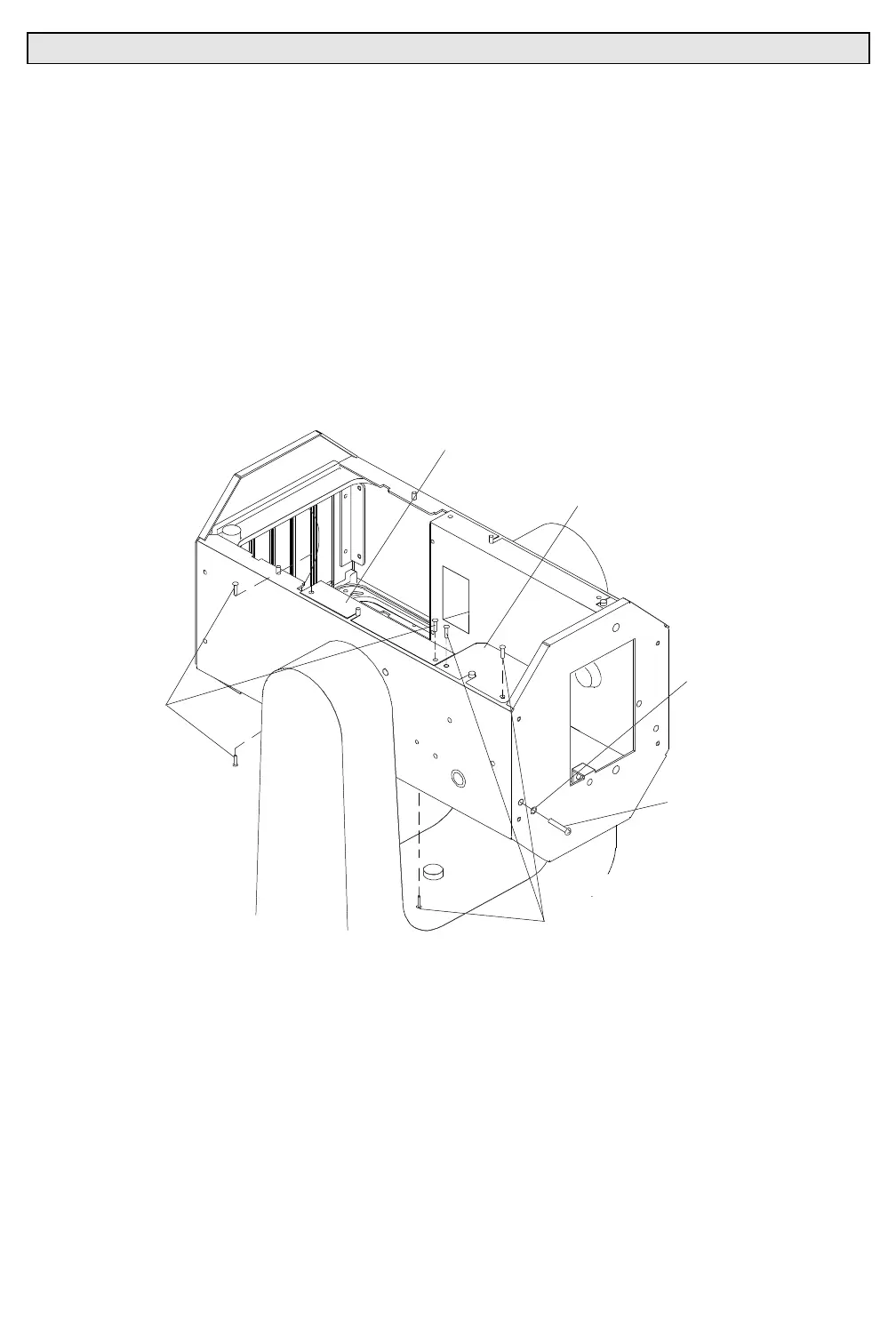
Step 10. Remove pulley side rail cover and tilt mechanism cover.
a. At pulley side rail cover, remove three 6-32x5/16"PPB
screws that secure pulley side rail cover to side rail and
remove cover (
Figure 3-24
).
b. At tilt mechanism cover, remove three 6-32x5/16"PPB
screws that secure tilt mechanism cover to side rail and
remove cover.
PULLEY SIDE
RAIL COVER
TILT MECHANSIM
COVER
#8 BLACK
FLAT WASHER
RCOVREMV
8-32X5/16"PPB
SCREW
6-32X5/16"PPB
SCREW
8-32X1"PPB TILT
ADJUSTMENT SCREW
MECHANISM
Figure 3-24. Pulley Side Rail and Tilt Mechanism Cover Removal and Replacement
Step 11. Remove tilt mechanism.
a. At rear cover, remove 8-32x1"PPB tilt mechanism
adjustment screw and #8 black flat washer.
b. At pulley side rail, remove three 6-32x3/8"PFB screws, #6
flat washers, and 6-32 KEPS nuts that secure tilt mechanism
to pulley side rail.