C
HAPTER
1. I
NTRODUCTION
1-19
02.9628.0010 CONFIDENTIAL
7-Oct-97
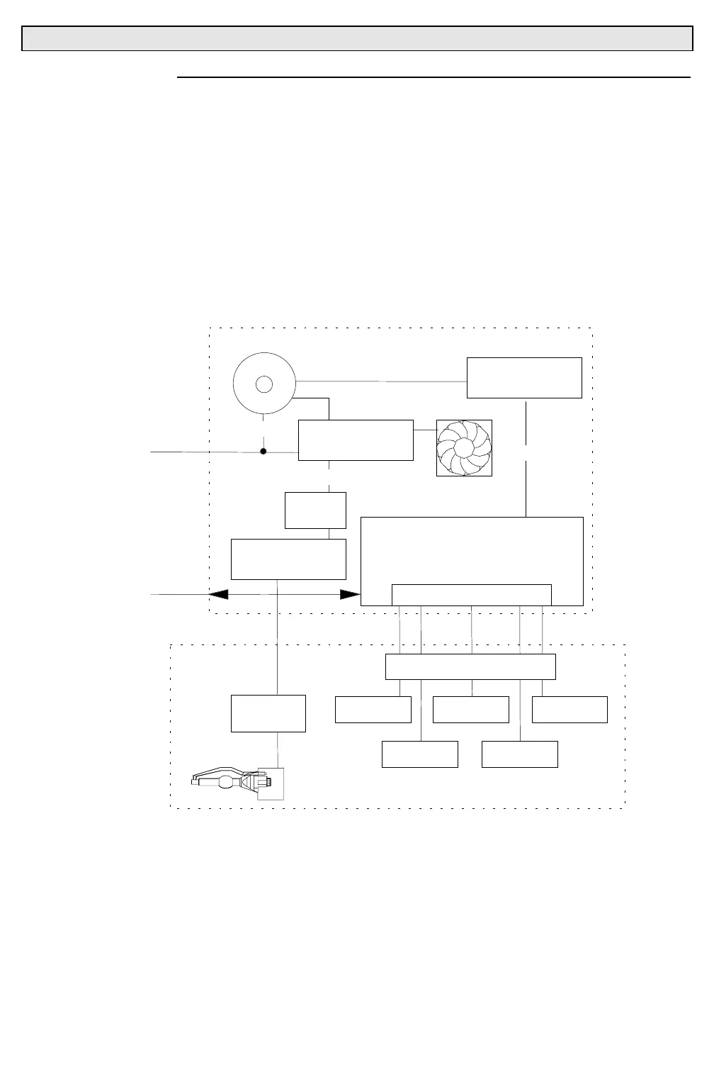
1.5.3 Data and Power Flow Diagram
Input data and power is supplied to the luminaire via the
Series 200
connector on the electronics chassis. Power is directed to the voltage
select board (VSB). The VSB switches the transformer primaries for the
appropriate mode. Power is distributed to the APS power supply, which
supplies operating voltage for the lamp, and the low voltage supply, which
supplies DC voltage to the control boards. Control boards receive power
and data, distributing to the main mechanical assemblies located in the
luminaire head assembly.
FAN
DATA IN
VAC IN
UNIVERSAL CONTROL BOARD
INTERFACE BOARD
MOTHERBOARD
MOTOR DRIVERS
LOW VOLTAGE
SUPPLY
XFMR
ELECTRONICS
CHASSIS
DIMMER
PAN TILT BEAM
COLOR
LAMP
IGNITOR
PCB
VAC
VDC
HEAD ASSEMBLY
EMI
FILTER
APS POWER
SUPPLY
VOLTAGE
SELECT BOARD
VAC
YOKE TERM. BOARD