C
HAPTER
3. M
AINTENANCE
P
ROCEDURES
3-9
02.9628.0010 CONFIDENTIAL
7-Oct-97
3.1.8 Test Setup
To install test EPROMs and test luminaire:
Step 1. Remove luminaire from system installation.
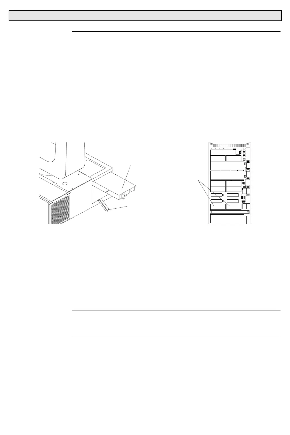
Step 2. Remove lamp control assembly.
a. At right chassis air filter, while pressing down on filter, pop
out top of filter from chassis and fully remove filter.
b. Remove four 6-32x5/16”PPB screws that secure right top
cover to chassis and remove cover.
c. At card retainer, press down on spring release and open
retainer. Remove lamp control assembly.
LAMP CONTROL ASSEMBLY
CARD RETAINER
LO HI
TEST EPROMS
Step 3. Install test EPROMs.
a. At universal control board, using IC extractor tool, remove
system EPROMs.
b. Install HI and LO self-test EPROMs.
1. HI EPROM (87.7137.0001).
2. LO EPROM (87.7137.0002).
Step 4. Re-install lamp control assembly. Close chassis lid.
Step 5. Set thumbwheel address to 000.
Note
: Power is immediately sent to luminaire when cheater cable is
connected. Do not connect cheater cable to luminaire until ready to
perform tests.
Step 6. Obtain cheater cable (local 3-pin power connector on one end
and a 9-pin CPC connector on the other) to supply power to
luminaire. Connect 9-pin CPC of cheater cable to
Series 200
connector at luminaire chassis. Luminaire should calibrate and
then stop.
Step 7. Set thumbwheel to desired test. Refer to Test Results Charts
section.