3-82
V
ARI
*L
ITE
®
-
VL4
W
ASH
L
UMINAIRE
S
ERVICE
M
ANUAL
CONFIDENTIAL 02.9628.0010
7-Oct-97
Step 4. Remove voltage selector PCB.
a. At VSB, from outside of chassis, remove 4-40x5/16"PPB
screw that secures PCB to chassis (
Figure 3-29
).
4-40X5/16"PPB
SCREW
VOLTAGE
BOARD
SELECTOR
Figure 3-29. Voltage Selector PCB Removal and Replacement
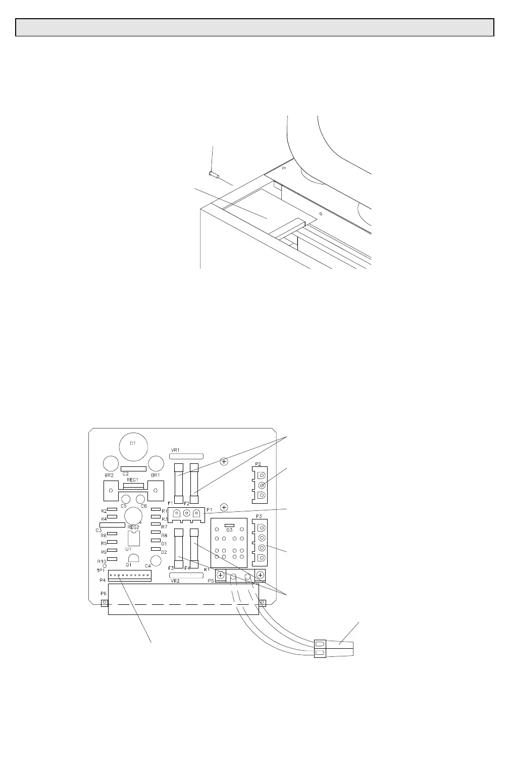
b. Disconnect the following connectors from top of voltage
selector PCB (
Figure 3-30
):
1. 3-pin MATE-N-LOK connector from P2.
2. 4-pin MATE-N-LOK connector from P3.
3. 3-pin MATE-N-LOK connector from P1.
4. 12-pin MTA connector from P4.
c. At bottom of VSB, disconnect red, 2-pin connector and
remove PCB.
3A FUSES
3-PIN
MATE-N-LOK
CONNECTOR (P2)
4-PIN
MATE-N-LOK
CONNECTOR (P3)
10A FUSES
10-PIN MTA100
CONNECTOR (P4)
3-PIN
MATE-N-LOK
CONNECTOR (P1)
2-PIN
SERIES 30
CONNECTOR
4VSBVW
Figure 3-30. Voltage Selector PCB Parts Location
Step 5. Replace voltage selector PCB by doing Steps 2 thru 4 in
reverse.